If you do much freehand drawing with the pencil tool, I’m sure you’ll appreciate the Illustrator 25.3 update with the new canvas rotation feature. In preliminary testing, most Graffix plugins seem to work fine, with one notable exception.
In AxoTools under macOS Mojave, some panel controls such as dials, the Projection panel’s proxy cube, and the list in the Transformations panel appear blank. I’ll address these as soon as possible, but it will likely have to wait an update to the CORE libraries these plugins are based on. If this affects you, you may want to either update your OS or hold off on updating to AI 25.3, or also keep a second older version of Illustrator on your hard drive for when you need to use those AxoTools controls.
Compatibility with Apple’s new M1 processors is also expected in a new CORE update, but no availability date is available.
AxoTools is not a 3D application, but tries to assist illustrators in achieving a 3D look the best it can. Simple shapes are pretty straightforward, but complicated shapes can wind over and under each other like an Escher drawing. In that case, AxoTools evaluates the paths and makes its best guess on correctly stacking the pieces.
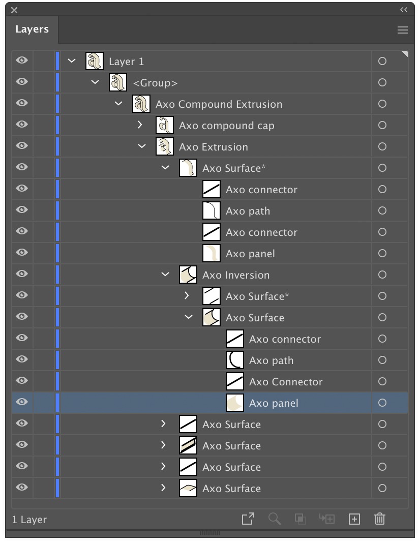
When a path is extruded, AxoTools creates closed paths for fillable areas and open paths of multiple stroke weights. To make things more easily edited, the pieces are organized into groups. In the Layers panel, you can expand these groups to find the pieces you may want to edit. Compound paths contain elements nested inside of other elements, so things get a bit more complex.
The front surface is named as a “cap,” and is placed above all of the edge pieces. The edges, which give it depth, are divided into surfaces. Each surface is composed of fillable “panels,” stroked “paths” that follow the original path’s shape, and “connector” pieces for corners that connect the front cap to the rear cap (the rear cap and hidden surfaces may or may not be drawn depending on your Extrude panel settings).
This is not an animation, but a screen recording right out of Adobe Illustrator! Each face of this dodecahedron is a live Transformation object created from the same pentagon shape, with movements and rotations added in the AxoTools Transformations panel.
Sure, it’s unlikely you’ll ever need a shape like this, but we often need art rotated away from our usual three planes. This demonstrates how, whether it’s a skylight, an instrument panel, or graphics on a milk carton, that task is now a whole lot easier!
You can download this file from the link at the end of this post and with AxoTools installed, even in demo mode, examine how this crazy “disco ball” was built.
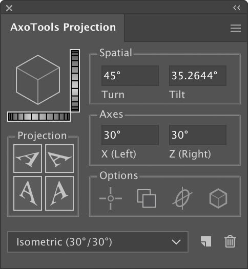
Each facet is made from a pentagonal path, turned into a live object that specifies its movements and rotations. The orientation is set relative to the current AxoTools projection, so in the AxoTools Projection panel you can adjust the settings with the dial controls to see the dodecahedron rotate as a unit in real time!
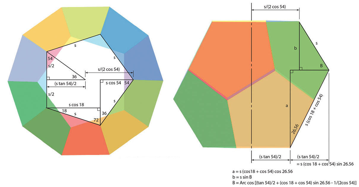
When Ron Kempke built this, he used his math superpowers to determine the angles and offsets.
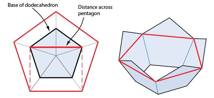
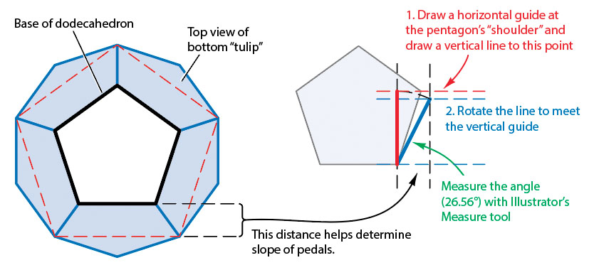
But fear not! For those who would rather not break out a scientific calculator, it’s possible to let Illustrator do most of the heavy lifting. First, make a copy of your base pentagon to create some guide art. Imagine the dodecahedron as two “tulip” shapes placed face-to-face. We know that the shape across the “shoulders” of the tulip would be equal to five segments equal to the width across the base pentagon. That will allow us to draw a top view of the shape.
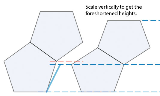
The offset from the base pentagon to the section at the shoulders tell us the foreshortening of the slope of each “pedal.” Draw vertical guides this distance apart. Draw a vertical line from the base of the pentagon to the height of its shoulders. Rotate this line until its width matches the offset distance in the top view. Measure the angle of this line (26.56° in this case) for use in the Transformation objects later. Draw a horizontal guide at the top of this rotated line.
Copy the pentagon and rotate the copy 180°, then position it so each pentagon’s tip and shoulders match as shown below. Select the pentagons and scale them vertically, using the foreshortened height of the rotated line as a guide.
This art, of course, isn’t a real side view, since the upper and lower pieces would be horizontally scaled and sheared differently. We’re only interested in finding the foreshortened vertical dimensions in order to create our Transformation objects.
With these principles in mind, click the link below to download Ron’s file and examine the settings in each piece.
Update: now with AxoTools 16.2, there’s an easier way!
Ron Kempke, who wrote the math behind AxoTools, has provided a follow-up to this post on using an auxiliary view in AxoTools, with these steps on taking it a step farther. Even with the oblique plane rotated at all three axes, we can still construct an auxiliary view and establish an axis for extruded art on that plane.
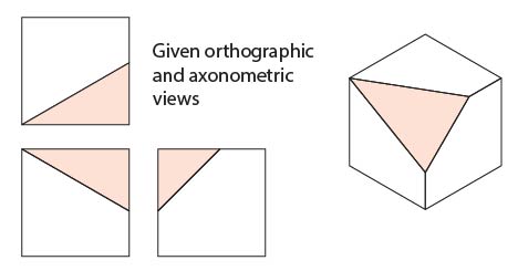
In this example, we have a simple cube with one corner removed. With the three sides projected, the triangle shape practically draws itself, but a problem arises when other objects need to be added that match this orientation.
Here, Ron walks us through this process using the AxoTools Projection panel along with Illustrator’s built-in Scale and Rotate tools.
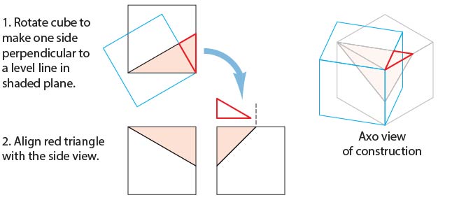
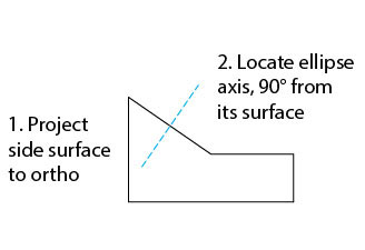
To start, we need to do some construction drawing in the orthographic top view. You’ll probably want to work on copies of these views. Select the long side (hypotenuse) of the triangular shape in the top view. Copy and paste it, then rotate it 90°. Position this line to divide the shaded triangle at its right-angle corner at the corner of the cube. Use this as a guide to draw the red guide triangle.
Align the right angle of this triangle with the upper left corner of the right side view. Rotate the top view to match the guide triangle, as shown in the blue square below, then project this to the axonometric top view.
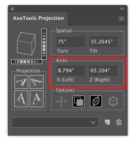
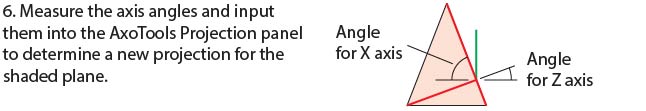
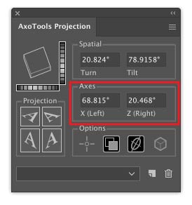
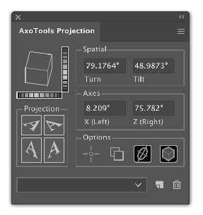
Use Illustrator’s Measure tool to measure the angles of this projected shape. Enter these values into the Axis fields of the Projection panel, which will then become a new (but temporary) axonometric view. The top face of the preview proxy cube in the Projection panel should resemble the rotated cube in your art. Note that these values are for this example only; your angles will certainly be different. If you now project the left and right ortho views, it should resemble the blue cube shown above.
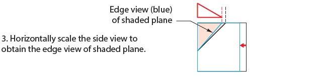
Select the right orthographic view and scale it so that the shaded triangle matches the width of the red guide triangle.
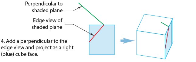
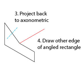
Now on this foreshortened right side view, rotate a copy of the angled line -90° as shown. Here it’s colored green to distinguish it from red guide lines. Remember that having entered new values into the Projection panel axis fields, your projection now matches the blue cube shown below. Project the new guides into your axo view.
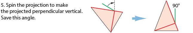
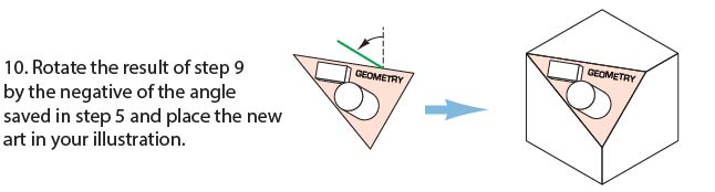
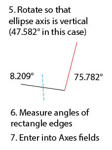
Measure the angle of the green guide line that represents the perpendicular, and save that value for later. Rotate the oblique surface and red guide lines so that the perpendicular is perfectly vertical.
If you’ve entered the new X and Z axis angles correctly, the top surface of the preview cube will be oriented at the same angles as your red guide lines.
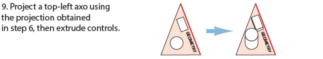
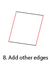
You now have an orthographic (top-left) view of your oblique surface! Add your additional details. It’s worth noting that the red guide line at the top corresponds to the upper edge of the surface on the top view.
Now extrude any objects on this surface, along the vertical axis. You can do so visually with the Extrude tool, or numerically with the Extrude panel (be sure to check the Foreshorten option). If you have a left or right view showing the depth of the objects on this view and you’ve placed reference points for these views, you can drag by reference in the side view and the depth will be measured and foreshortened for you. (If you extrude a shape on this surface numerically from the Extrude panel, you should be aware that normally objects at this angle recede, so you’ll have to rotate it 180°.)
If you’re using reference points here, remember to redefine them in your standard ortho views when you’re finished with these details.
Finally, set your projection back to isometric or whatever projection your overall illustration used.
In review, the basic steps are:
Find the plane’s perpendicular from the top view.
Define a projection along the top perpendicular to find the plane’s side perpendicular, which is also its extrusion axis, from a side view.
Spin the oblique surface so that its extrusion axis becomes vertical.
Define another projection based on the rotated guides and un-project the oblique surface.
You now have an ortho view of your oblique surface that you can add details to, and save for future reference.
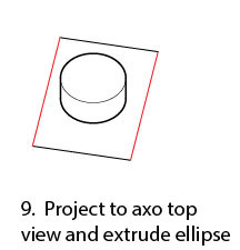
Project a top-left axo view and extrude any objects on that surface.
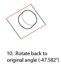
Spin the oblique surface back to its original orientation.
Many thanks to Ron Kempke for this useful and fascinating exercise!
Update: Now with AxoTools 16.2, there’s an easier way!
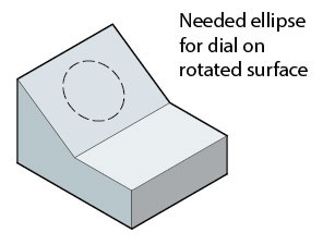
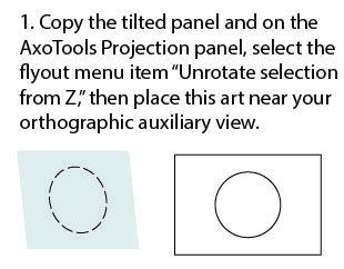
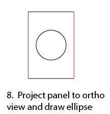
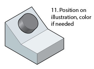
Every technical illustrator, it seems, eventually runs into a situation where a surface they’re drawing doesn’t exactly match the top, left, or right views. If one edge of a rectangle that defines that surface coincides with the X or Z axis, there are at least two ways to project that angled face. Let’s say you want to add a dial or knob to this control panel.
In conventional drafting, you’d draw what’s called an auxiliary view for the tilted panel, then mathematically calculate the locations of the panel’s elements in the axonometric (or isometric) view. One way might be called the “rotate and force-fit” method.
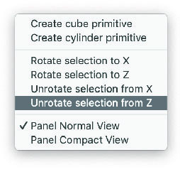
Here’s a sequence of steps that shows how that works, and illustrates the reason those four “Rotate” and “Unrotate” items were added to the flyout menu.
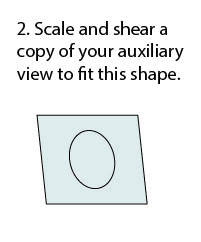
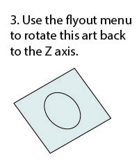
Of course, the axis of the ellipse is at a different angle than any axis, so here’s a method that uses axonometric logic to reverse-engineer the projection of that surface in order to use the Extrude tool to accurately draw the cylindrical shape of the knob.
After this technique, be sure to restore your axonometric projection to the previous settings!
New tools are currently in progress for AxoTools, but until they’re available, this should help you get through some of those unusual situations.
The process of doing isometric/axonometric drawings in Adobe Illustrator really hasn’t changed much since the mid 1990s, or even since the late 1980s, something I hadn’t fully realized until doing the first AxoTools video. How many of you can relate to this?
Working in Illustrator 88, I would project art to isometric by manually doing the scale-rotate-scale method. When the QuicKeys keyboard macro utility came out, it automated that process and also allowed me to change the constrain angle by pressing an otherwise-unused function key.
In 1994, when Illustrator 5 added support for plugins, I wrote one called Isometric that I shared free on my web site. It added menu items to project art to and from isometric planes, and to create box and cylinder primitives. Does anybody recall using this? I also wrote a free companion plugin Isometric Line Tool to draw straight lines in isometric, which was around quite a while and later merged into AxoTools.
In 1998, Illustrator 8 added recordable Actions, which was easier to maintain than updating the plugin as Illustrator’s API became more complicated. It also added Smart Guides, which I relied on when QuicKeys had compatibility issues with operating system changes.
About this time, Adobe had a simple 3D app called Dimensions (not the same as their current Dimensions product) that exported shapes to a file Illustrator could open. This app was the origin of the “Off Axis” projections I use in my Actions and in the current AxoTools presets. I used Dimensions in my first locomotive cutaway rendering. Unfortunately, it didn’t last long. Some of you may use SketchUp in that same way today.
Has anybody found Illustrator CS’s 3D effect actually useful for scale isometric drawings? I had high hopes when it appeared, but it never proved truly useful to me.
Hot Door’s CADtools has had support for isometric for several versions now, and in recent years supports axonometric views. I’ve found CADtools indispensable for technical drawing, but knew there had to be an easier way to assemble the pieces.
So for over 30 years, the process has been to project a shape to an isometric plane, then manually move it into position. This worked OK when one plane served as a sort of floor plan that other shapes could be snapped to, but it didn’t work well for most things I drew, like vehicles, machinery, and electronics. In order to get objects positioned correctly, I often drew a temporary “armature” with projected lines along two or three axes.
I’d actually envisioned today’s AxoTools plugin decades ago, using virtual armatures to position art and tools with custom constraints to move art along any defined axis. Using geometric formulas by Ron Kempke, it became possible to add support for any axonometric projection showing the left, right, and top views. Why it took so long, I’m sorry I can’t answer. I hope you agree that doing axonometric drawing in Adobe Illustrator is significantly easier than ever with AxoTools.
I was recently contacted by Iván Gómez about doing videos on my plugins. Iván is a certified Adobe instructor in Columbia who has done many other videos on various aspects of Illustrator, Photoshop, and InDesign, which are available on YouTube. He chose to do a video on AxoTools, which is very informative. I have an AxoTools video in progress also, but it won’t be available until after the next AxoTools update featuring a few new tools.
If you’re interested in AxoTools, please watch this as it demonstrates some important concepts:
Overview of isometric, dimetric, and trimetric projections
Setting and changing the orientation of your projection
Placing and moving common reference points
Projecting using buttons in the panel, using menus, or custom keyboard shortcuts
Moving objects in the axonometric view by dragging in an orthographic view
Using the AxoDraw tool to draw constrained lines
Using the AxoScale and AxoRotate tools to modify projected art
Viewers can also benefit from a coupon code shown in the video, good for 20% off any Graffix plugins during August 2020.
Thanks, Iván, for doing the video I must confess I should have done months ago!
If you create technical illustrations, you probably use CADtools. I use it, and wouldn’t consider doing the work that I do without it. There are times, however, when I wish I had tools that are a little less technical and let me work more visually. Then again, I still need precision, especially when it comes to getting the pieces of a technical drawing correctly oriented to each other. I have drawings, of course, that show these spatial relationships in top and side views, but how does one translate that to Illustrator artwork?
I established a couple of rules for my plan. OK, guidelines, but firm guidelines. I really don’t want to measure things and type numbers into dialogs. Even worse, I don’t want to then have to do math on those measurements to account for foreshortening and other factors. Over time, a method of achieving this slowly took shape.
It all hit critical mass when I met Ron Kempke. Actually, he found me, asking if I could write a plugin that simplified entering into Illustrator the equations he’d worked out over decades of doing technical drawings. His samples were definitely cool, but it was a real stretch for me to grasp the meaning of Sigma, Psi, Beta, Gamma, and an assortment of Greek characters he used to define these concepts. After a few conversations and exchanges of annotated diagrams, it looked pretty hopeful for translating those equations into C++ code, then wrapping a user interface around it to let illustrators like lazy me use the math without having to think about it. And not just for isometric, but for any off-axis view one may want.
Enter AxoTools.
The gist of the idea is that illustrators identify common reference points in each view of their drawings that refer to the same point in 3D space as well as a point in the axonometric view that’s comprised of those drawings. As a result, we can make some otherwise cumbersome things happen quite easily.
Artwork projected to a corresponding plane can be created in place so that the adjoining surfaces automatically meet where they should.
Artwork can be created wherever it’s convenient, then moved or modified by dragging a tool a corresponding distance and direction on an ortho view.
When one reference point is moved, all other reference points are automatically moved accordingly so relationships between them last.
A few other tools are included to round out the package:
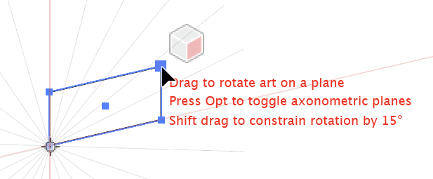
Axo Rotate tool allows you to rotate an object within the axonometric plane it’s in. The tool displays a protractor for that plane, and allows you to press Shift to constrain the rotation to increments of 15 degrees.
Axo Scale tool can scale an object along the X, Y, or Z axis.
Axo Draw tool draws lines constrained to the current axes, automatically concatenating them as you go.
The Axo Tool that defines and moves reference points also moves selected art or individual anchor points constrained to the nearest axis.
Questions? Concerns?
I have too many panels hogging my screen space, so I don’t want to add still more. No problem, you can collapse the panel to just the projection options and do your projections with menu commands.
Navigating menus is too slow, and I want to work quickly. No problem, part of the purpose of having menu counterparts is to enable keyboard shortcuts. This makes the process very quick!
Scrolling around a large artboard between the various views is cumbersome with or without AxoTools. No problem, AxoTools adds menus for quickly going to any of your defined views, and using keyboard shortcuts, that’s now very fast.
Can I define my axonometric view in CADtools and use AxoTools to project and position my art? Yes, AxoTools can import the axonometric settings from CADtools 11.01 or later. AxoTools was designed to complement CADtools by providing a more fluid way to work, alongside the precision of CADtools.
Can AxoTools export my projected art to a 3D file format? Sorry, no, AxoTools is not real 3D for Adobe Illustrator, but its tools for projecting and moving art make it a lot easier for technical illustrators who need to think 3D in a 2D environment.
AxoTools is now available on the plugin download page, available for Illustrator CS6 and CC for Mac and Windows. I hope you find it as indispensable in your workflow as I find it in mine!
 AxoTools is not a 3D application, but tries to assist illustrators in achieving a 3D look the best it can. Simple shapes are pretty straightforward, but complicated shapes can wind over and under each other like an