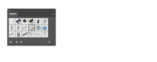
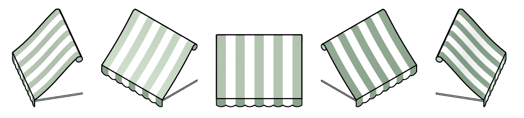
PopArt symbols can be dragged from a symbols panel and AxoTools will automatically expand them to fit your choice of axonometric planes in your current document projection. This includes extruded art, art with compound rotations, and with moves along axes.
For example, say you’re building an axonometric village and you want awnings over some of your windows. Rather than build them, or copy and paste them from a previous project, you can store one as a PopArt symbol and drag them into your document as needed.
You’re not limited to just isometric, either. PopArt will expand and conform to any face in any document projection you set, including an auxiliary projection.
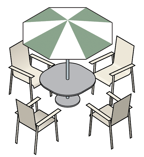
PopArt can contain several layered objects at various angles. In this illustration, only two PopArt chairs created the four seen here, and the table with umbrella is all one symbol.
Please see the AxoTools documentation for more information on creating and using AxoTools PopArt symbols. And please let me know if you create PopArt symbols you’re willing to share with others!
Illustrator users know that we need panels to access controls and options, but it quickly fills valuable working screen space. Collapsing panels to icons helps, but repeatedly opening and closing them can be a hassle, as well. One option Adobe brilliantly engineered for Illustrator is the control bar that shows a limited number of essential controls consolidated into in a thin strip.
The newest version of AxoTools now includes a control bar as well. You can access it in the menu Window > AxoTools > AxoTools Control.
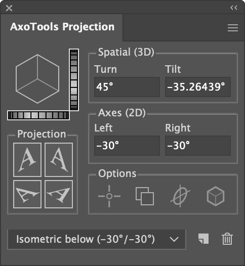
The first item shows at a glance the projection of the current document. Double-click it to open the Projection panel to change it. Next is a label showing the current document’s scale ratio and units used in AxoTools’ panels that calculate scale measurements. Again, double-click the label to open the Preferences dialog to change the scale or units.
Next is a series of four buttons to project or unproject art, which work exactly like the buttons in the Projection panel.
The next set of four buttons control options that affect projecting and other functions. The first one selects whether reference points are used. This one has a blue background when active to make it easier to spot since you would normally want to keep this option off unless you are busy projecting art from various ortho views to an axonometric view as described here.
The next option controls whether to automatically project a copy of the selected art. The third button chooses whether to rotate ellipses so that the anchor points align on the major and minor axis when projected. Fourth is the option to apply properties in the Draw Settings panel when projecting art.
At the far right is a shortcut to open AxoTools’ online documentation.
Are there other items you would like to see included here? They could static like these controls, or dynamic — visible only under some conditions. Let me know what you need!
If you adjust the Tilt value of your projections using the dial control to the right of the proxy cube image, you’ve possibly found that it now allows you to tilt far enough to show the bottom of the cube. You could also just enter negative values for the left and right axes, or a negative Tilt value.
When that happens, the projection buttons change their orientation to make sense for the inverted view, including moving the “top” buttons to below the sides for “bottom” projections.
The left and right axes will now both show as negative values.
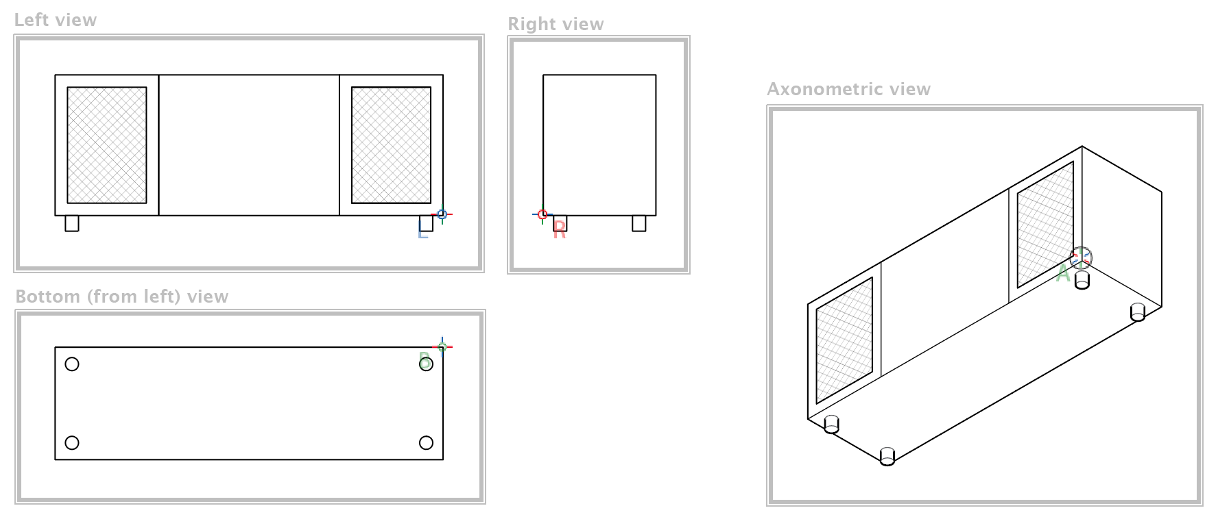
In this example, how many of you had one of these in your living room growing up? Stereo consoles were quite the rage in 1970, but were replaced with component-style equipment not long afterward. It provides a good example of an underside view, to show the location of the four feet.
In this case, I’ve defined the four zones, which now need to include options for bottom-left and bottom-right zones, as well as bottom reference points. In most cases, you really won’t need to define zones, but if you have large or complex ortho views that you move or extrude by reference, it can save you from some unexpected behavior later.
While revising the Zone tool and zone creation, it seemed a good time to make other improvements to the Zone tool and its functions to make the process easier and more intuitive. Reference points are now visible while the Zone tool is active, and they can be created here now, as well. Rather than draw a rectangle every time, you now have the option of selecting art from an ortho view, and the tool will draw a rectangle to enclose it. Other details are available in the updated documentation for the tool.
To summarize, the Projection panel now supports Tilt and Turn values that show many combinations of the left and right planes, plus the top or bottom.
Now, this may be going kind of crazy, but it would be possible to add the option to project art to a back surface. This might look like a sign painted on a window, but appearing backward as viewed from inside the building. Would that be useful?
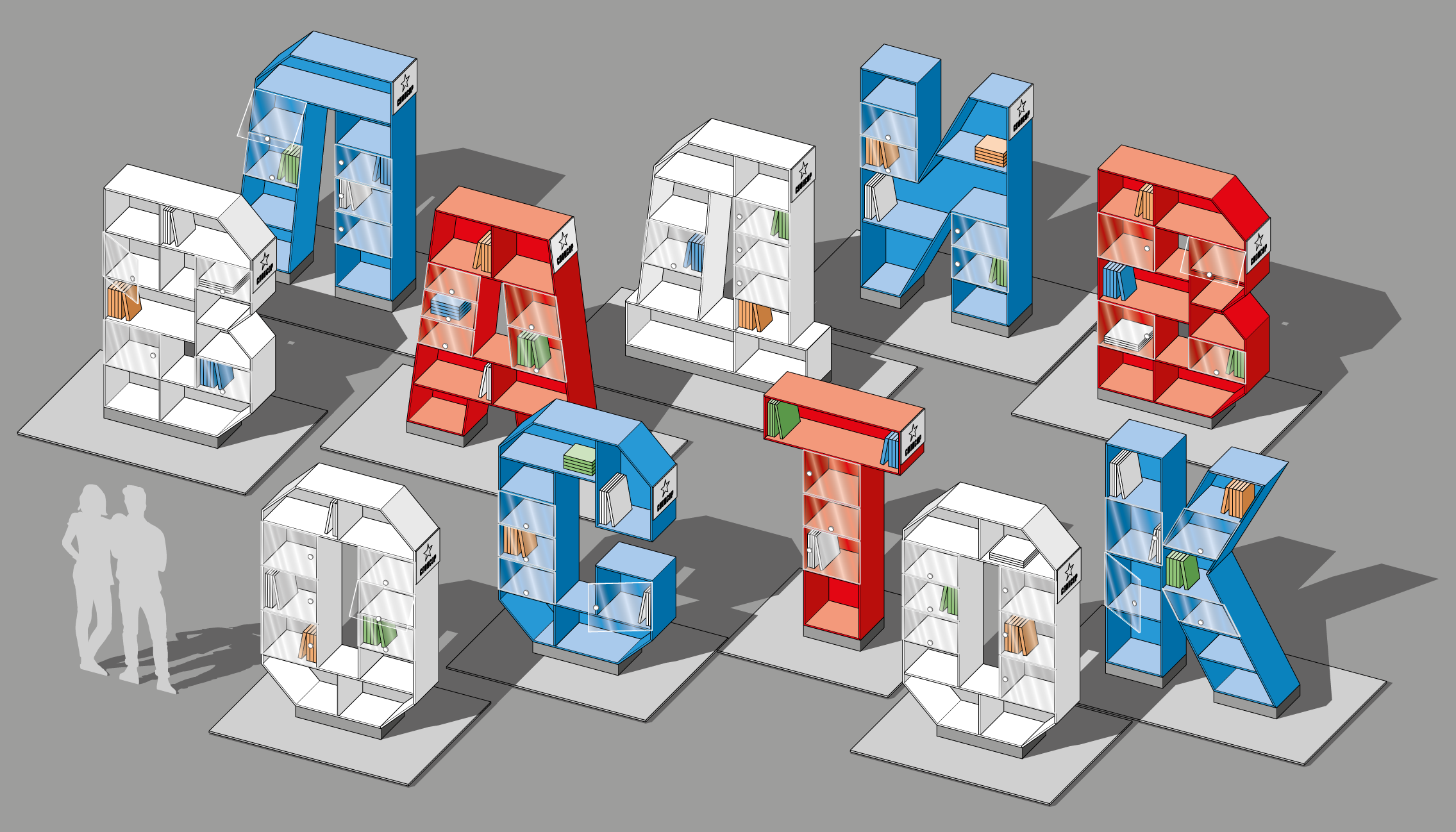
Illustrators all over the world have been creating amazing work with AxoTools. You can see a sampling of them in the new AxoTools Gallery. Many thanks to all who contributed. One of the entries is shown below.
Library book shelf modules, Vladivostok, Russia
These bookshelves in the form of Cyrillic letters were designed by Egor Chistyakov. He started with the shelf front surface as a compound path, then extruded with multiple line weights and shaded color. Shadows and other details were added.
First, I’d like to thank everyone who participated in the AxoTools survey. The meaningful comments are already making a difference in AxoTools’ features and documentation.
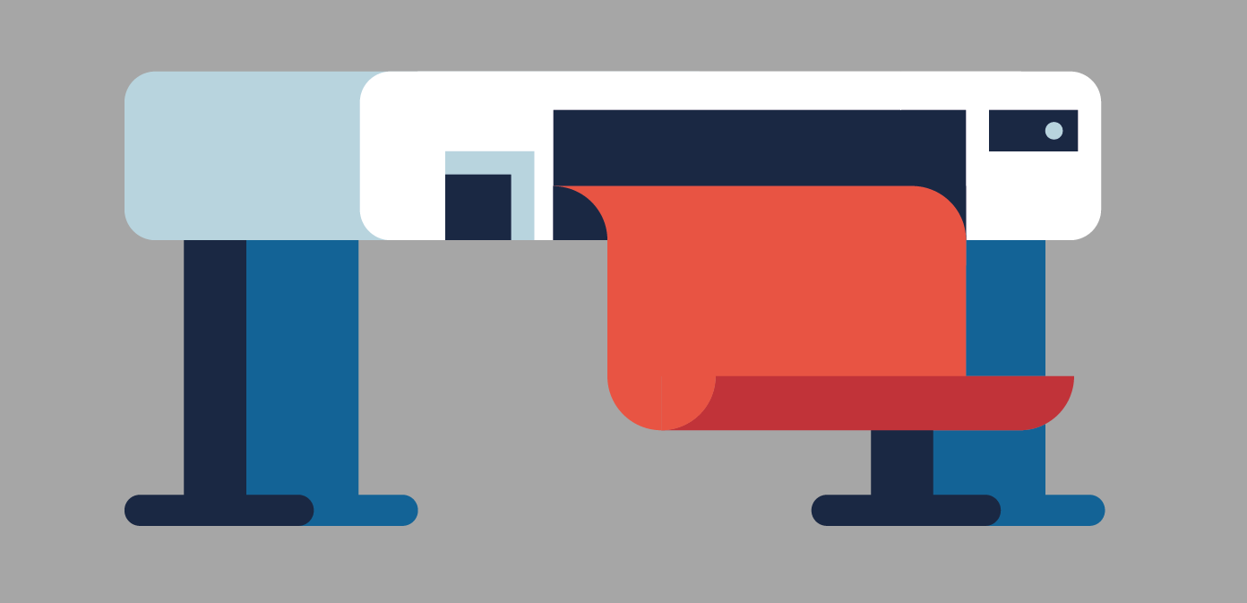
The most surprising thing was the number of users who wanted to extrude horizontally for a stylized drawing such as this one by Dörte Roßmann.
That seems like a natural thing for AxoTools to do, but we can’t forget that the plugin’s core function is to help illustrators work in views like isometric, dimetric, and trimetric where we see three surfaces, not two. It has never been a design tool, although there’s nothing wrong with bending the rules a bit to accomplish some design effects as long as it doesn’t hobble the plugin’s primary purpose.
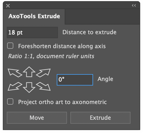
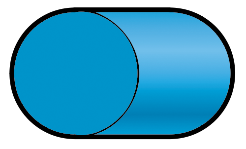
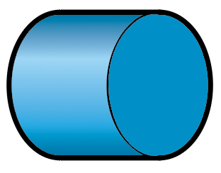
Horizontal extruding has been available using the Extrude panel. Just set the angle to 0 and leave the option to project the art unchecked. That gives you something like this:
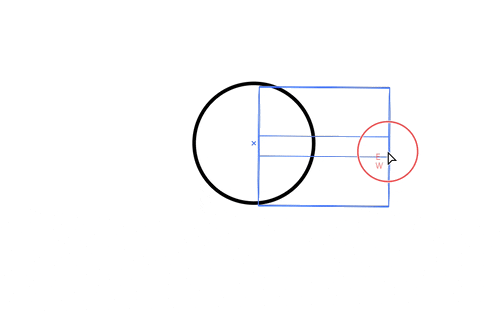
If you projected the art with a 0° angle, you’d simply get a rectangle. The reason for this is that the Extrude panel, like the Extrude tool, work in the context of the current projection. If you drag a circle with the Extrude tool while holding the Cmd or Ctl key for a freeform angle, you’ll see that at a horizontal angle, all you see is a side view of your original shape.
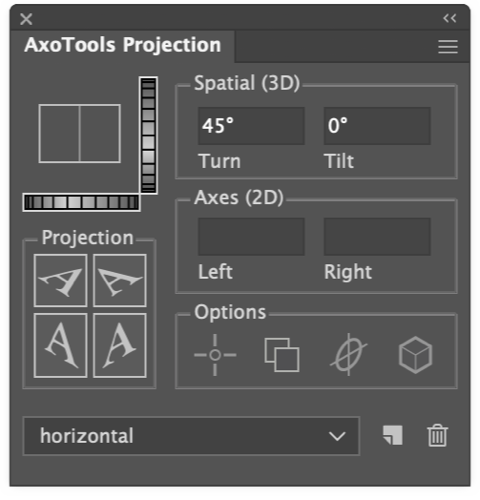
To make things easier for people working with horizontal extruding, the Projection panel in the latest free update to AxoTools now supports broader Tilt and Turn values, which allows you to do a full-fledged horizontal extrusion.
Previously, values of 0 or 90 were not allowed for Tilt or Turn because they essentially hid one or even two of the three axonometric planes. Now, using a Tilt value of 0, or Turn value of 0 or 90, will disable the X and Z axis fields because there must be an incline on both axes in order to calculate the tilt and turn — in a case like this, the turn value is ambiguous. A Tilt value of 90 is essentially a top axo view, so Tilt is limited to 89°.
It’s important to understand, too, that at projections where the X and Z axes overlap, horizontal extruding is always on the X axis, so using the Extrude tool, the edges always drag out to the left. Can that be “fixed” to allow horizontal extruding to the right? Well, yes, if we add complications to an interface that some people say is already way too complicated. A workaround is that, with a Tilt value of 0, the Extrude panel extends your path to the left, while with other Tilt values, the panel extends it to the right.
In response to user requests, you can now press Shift when dragging with the Extrude tool to constrain to right angles. That won’t give you the above effect, though, because it’s constraining a freeform extrude. That is, it’s calculating what that shape looks like within your current projection, not a shadow effect.
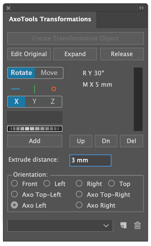
If you truly want to go completely independent of the document’s current projection, you can always use the Transformations panel, which allows you to rotate and extrude your art in any orientation you like, be it upside-down or even backward.
Now you can record and play back actions that include many AxoTools functions, with the free update to AxoTools available online for Adobe Illustrator CC 2019 through 2023. Actions currently supported include:
Project art to or from an axonometric plane
Extrude, either from the tool or the panel
Axo Scale
Axo Rotate
Axo Shear
Axo Move
Axo Rectangle
Axo Ellipse
Actions will play back using the current document projection settings. That is, if you recorded moving or extruding an object along an axis of an isometric view, then changed your document’s projection, it would adjust to operate using the current projection. Action playback also honors your current draw settings and Projection panel options so old actions adapt to your current environment.
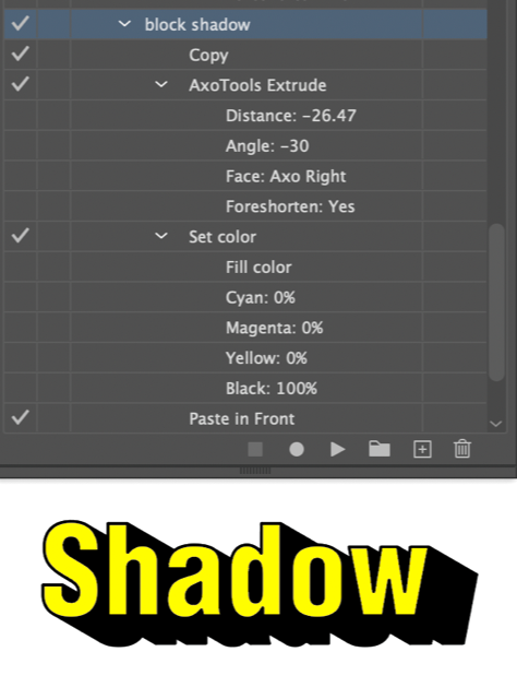
One example of using actions with AxoTools is a technique to do a block shadow effect (even though AxoTools was never made for that).
Select path art to which you want to add a shadow
Start recording the action
Select Edit > Copy
Extrude the art without projecting it, using either the Extrude panel or Extrude tool
Set the fill and stroke of the extruded and selected art to your shadow color
Select Edit > Paste in Front
Stop recording
Now any time you want to add a similar block shadow, just select your art and run this action!
I’m curious what ingenious actions other AxoTools users will come up with. Maybe one to construct a detailed hex nut? Please let us know in the comments below.
The latest update to AxoTools includes three improvements to shaded fills on extruded art. First, curved paths now have a gradient fill to more accurately show the curvature of the surface.
Second, the lighting is based on the location of a theoretical light source, so surfaces are shaded based on their actual orientation relative to the light, and no longer assigned a simple “top,” “left,” or “right” tint or shade.
Third, the light source is user-definable.
When you extrude a path, its fill color is used as the base color for shading values. For each base color AxoTools uses, it creates a gradient that’s stored in the document’s Swatches panel. To use your own gradient for shade values, just fill your starting object with the gradient and extrude it.
There is also a new panel where you can make adjustments to your light and shading, but it’s important to stress that you don’t ever have to fuss with those controls in order to use the new lighting and shading features. Most of you will probably want to stop reading here and just go download the update!
More for “explorers”
For those other few people in the room who want to take things a notch or two higher, the new panel works in three areas:
Gradient colors
Light location
Lighting properties.
At the top of the panel is a series of five color well widgets that represent the five stops on the shading gradient ramp for your current document color. The gradient itself represents the range of all possible colors to apply to your fills. AxoTools generates a shaded gradient ramp for each fill color you start with when you extrude with the shading option enabled.
The gradient represents the range of possible tints and shades available based on the angle of the lighting. The first gradient stop represents the lightest highlight color where the light hits it at a 90° angle. Using the default settings, the angle of light on the left isometric plane falls very close to the second stop, which is set to the original color. The third stop represents the shade when the light hits an object on its edge, and stops 4 and 5 represent the rear surfaces, with the last stop showing the effect of backlighting.
The light source’s location is defined with the familiar Tilt and Turn adjustments, which are relative to the viewer. Following these are slider controls for the light intensity, ambient light, and amount of backlighting. As you make adjustments to the lighting properties, the color wells along the top of the panel will preview the results of changes to the intensity, ambient, and backlight lighting properties.
At the bottom right, the “Reset to defaults” button will restore the default settings for all slider controls.
Below the color wells are two buttons relating directly to them. The “Rebuild gradient” button will generate five shades of the current document color.
The “Save gradient” button, I’ll confess, was included for the true “explorers.” If you changed the colors in the color well controls, either by changing lighting properties or using the color pickers in the color wells, this will overwrite the gradient ramp used for the base color.
Please see the online documentation for more information.
Today I released the first in a series of short videos covering topics relating to AxoTools, both using the plugin and doing technical illustration in general. The first video briefly describes different types of projections for the benefit of those who don’t come from a technical illustration background.
The next in the series will cover how to begin an isometric drawing in AxoTools. Other possible topics may include:
Using multiple line weights (including dashed break lines for curved surfaces) to suggest form and mass
Filling art with white to overlap parts
Using flow lines
Fill modes and other Draw panel options
What is that option to rotate ellipses when projecting?
Using the line tool to draw straight lines and to toggle line weights
Entering simple equations in text fields, plus auto-entry of measurements
Use the Extrude tool to draw a drop shadow (but never for an oblique projection!)
What’s the difference between the Transformations panel and Auxiliary projection panel?
Using the Measure tool
How does Project-in-Place work?
What are the Axo Zone tool and Projection Zones for?
If you have other suggestions for short video subjects, please leave a comment below!
AxoTools Qukck Tip: Projections
I’d like to thank Ron Kempke, AxoTools’ co-author, as well as Matt Jennings of Industrial Artworks, and Greg Maxson of Greg Maxson Illustration for the use of their illustrations and advice in getting this video series started.

 If you adjust the Tilt value of your projections using the dial control to the right of the proxy cube image, you’ve possibly found that it now allows you to tilt far enough to show the bottom of the cube. You could also just enter negative values for the left and right axes, or a negative Tilt value.