Click a link for more information on a tool
Essential tool
Tools to draw
Tools to modify
Utility tools
Axo tool
![]()
The Axo tool provides several functions related to positioning your art. It allows you to move art along an orthographic or axonometric axis. You can also create or move common reference points, which are used to automatically move art when it’s projected to or from an axonometric view.
Move art by dragging
If you drag the tool with art selected, it will be moved constrained to the current axes. Press the Option/Alt key to drag a copy of the art, rather than the original.
Move art numerically
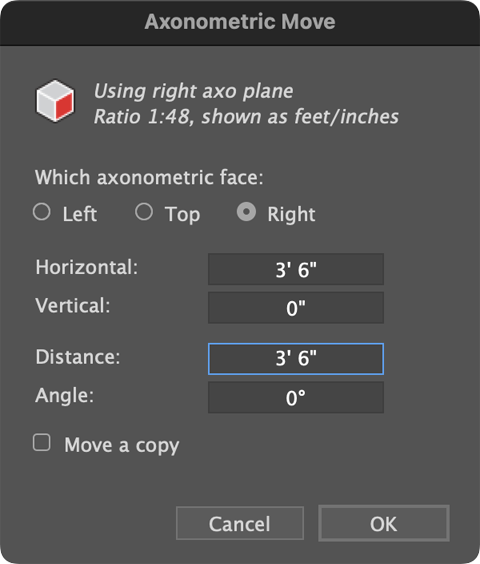 You can also move selected art numerically along an axis. Alt/Option click and the following dialog box will appear. Choose which axis you want to move the art along, then enter the numeric information.
Note that these values represent the flat, orthographic distance and angles, which are then projected for you. If, for example, you want to move an object to the upper right along an isometric Z axis, you would use an angle of 0, not 30. Let AxoTools do the math for you!
The current document scale/ratio is shown at the top of the dialog, as well as the current units AxoTools is using for the document, which may differ from the units Adobe Illustrator is using. Learn more about this in Preferences.
Move art by reference
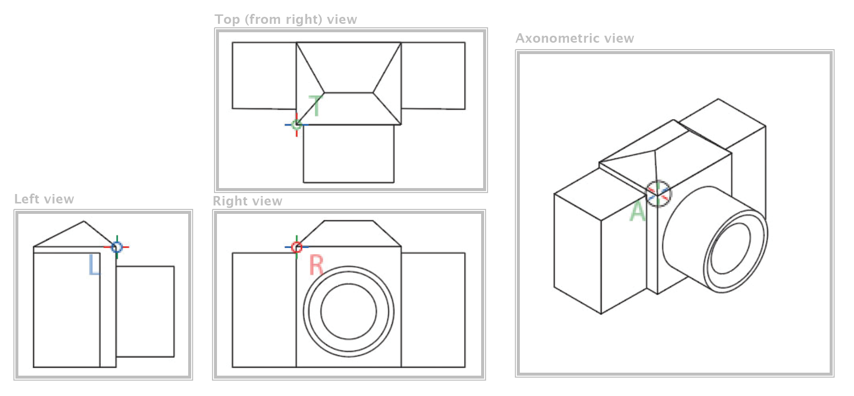
If axonometric art is selected and you drag in an orthographic view, the art will be “moved by reference” in the corresponding direction by the corresponding distance. This allows you to quickly and accurately position your projected art without tedious measuring and moving.
Note that to move by reference, as with projecting in place, you must first define common reference points.
Define common reference points
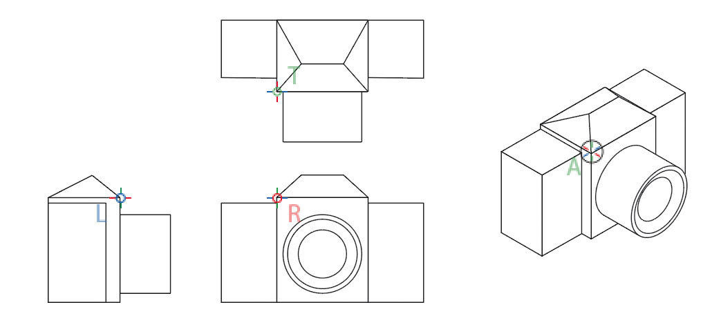
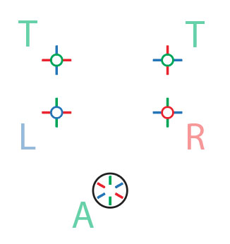
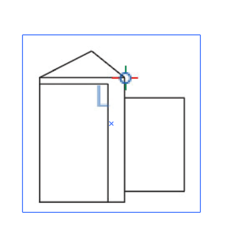
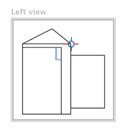
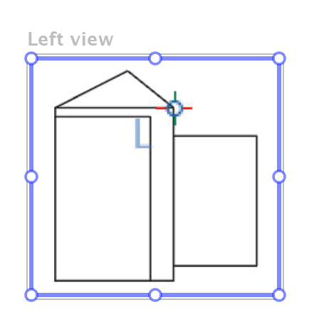
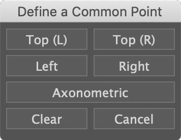 Click with the Axo tool to define a common reference point, which can be described as a point that represents the same location in each of your views. When the dialog appears, choose which view the point appears in, or click Clear to remove all defined reference points. Reference points are saved with the document, and when this tool is selected they will appear marked with a crosshairs symbol.
Move a common reference point
To move a reference point, click and drag — shortly after you’ve started dragging, press and hold the Cmd/Ctl key. As you move an orthographic reference point, note how all of the points move accordingly.
Menu navigation to views
Once you have defined a common reference point, you can quickly navigate to it again with menu items in View > Go to Axonometric View.
Place anchor points in a Transformations object
The section on the Transformations panel describes how to use the Axo tool to assign an anchor point for a Transformations object.
Project in place
 As you project art with reference points defined for both ortho and axo views, the axonometric art will appear aligned relative to the reference points. We call this “Project in place.” This is probably best explained with the introductory video below.
Axo Line tool
![]() The Axo Line tool allows you to click and drag to draw a straight line constrained to your axes, as defined by your Projection panel. This tool uses a set of path properties that is separate from the document defaults used by Adobe’s tools. It starts as black color with 0.5 pt. stroke width, round caps and joins, and no fill.
The Axo Line tool allows you to click and drag to draw a straight line constrained to your axes, as defined by your Projection panel. This tool uses a set of path properties that is separate from the document defaults used by Adobe’s tools. It starts as black color with 0.5 pt. stroke width, round caps and joins, and no fill.
Pick up a stroke style
To use a different stroke style, Option/Alt-click on another path with the desired settings — the cursor will change to an eyedropper. Note that only paths with a stroke applied will be read, and only the stroke width, dash, and color properties will be used (the fill will be ignored). All new paths created with the Axo Line tool will then have these path style properties.
Apply standard stroke weights as you draw
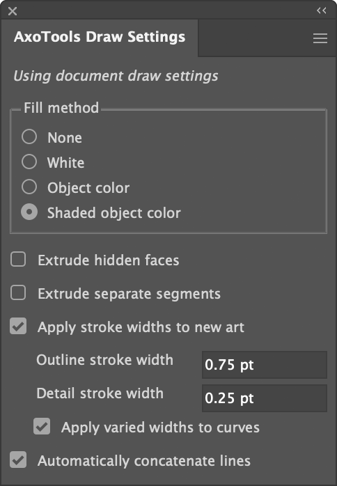
Several behaviors of the tool can be selected in the AxoTools Draw Settings panel found at Window > AxoTools > AxoTools Draw Settings.
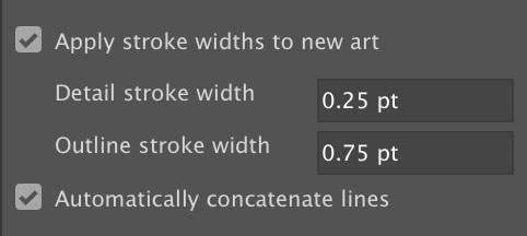
Check “Apply stroke widths to new art” to automatically apply one of two standard line widths you define in the Axo Draw Settings panel. Stroke weights can be specified in points or millimeters by typing “pt” or “mm” after the amount. These stroke weights will continue to display here, unless another is later specified, regardless of the current ruler units.
Toggle stroke weight
To toggle line weights between the detail and outline weight, click twice on a path. Note that only the stroke width will be changed, not its color, dash pattern, or other properties.
Automatically Concatenate paths
With the option to Automatically concatenate lines checked, you can draw a new path beginning at the endpoint of another path, and extend it as one continuous path. To temporarily reverse the setting, press Cmd/Ctrl after you start to drag the new path and continue to press until after releasing the mouse or stylus.
Override constrain to axis
While dragging with the Axo Line tool, paths will be constrained to the angles of the current axes. Press Shift to constrain angles to increments of 45° or press Option/Alt to create lines unconstrained.
Axo Tangent Line tool
![]() This tool draws a straight path tangent from another path. You can optionally connect it to another path, tangent to it also.
This tool draws a straight path tangent from another path. You can optionally connect it to another path, tangent to it also.
Draw tangent from a path
Axo Arc tool
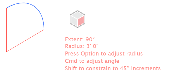
![]() As you drag with the Axo Arc tool, a new arc will be drawn. You can drag the arc forward or backward, left or right. Guide lines will appear to show the location of the arc center as well as a tangent line of the arc’s exit angle. If your preferences select Help text, the tool will also display the current arc’s extent angle and radius.
As you drag with the Axo Arc tool, a new arc will be drawn. You can drag the arc forward or backward, left or right. Guide lines will appear to show the location of the arc center as well as a tangent line of the arc’s exit angle. If your preferences select Help text, the tool will also display the current arc’s extent angle and radius.
 Modifier keys to control arc settings
As you drag, press the Alt or Option key to adjust a fixed radius, or press the Ctl or Cmd key to change the arc’s starting angle. Press the shift key to constrain the arc’s extent or angle to increments of 45°.
Create arc numerically
Click with the tool to display a dialog box to create an arc numerically. The Start angle represents the angle before projecting the arc to its axonometric plane, so you won’t need to hassle with converting angles on the screen to simple flat art. For example, a Start angle of 0° in the dialog would be drawn at 30° in an isometric top or right side view, and a 90° extent makes a quarter of a circle, regardless of the angles on the screen. Here, too, you can specify the radius of the arc with dimensions given in units you specify, such as feet or meters, and scaled to the current document ratio defined in your AxoTools preferences. Finally, choose whether the arc should curve to the left or to the right.

Axo Ellipse tool
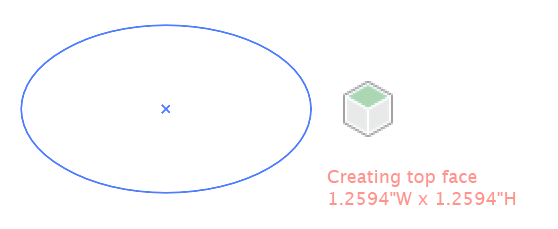
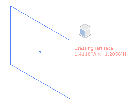
![]() As you drag with the Axo Ellipse tool, the ellipse will appear projected onto your current axonometric plane. If your preferences select Help text, the tool will also display the current width and height using the units specified in your preferences and scaled to your document scale.
As you drag with the Axo Ellipse tool, the ellipse will appear projected onto your current axonometric plane. If your preferences select Help text, the tool will also display the current width and height using the units specified in your preferences and scaled to your document scale.
 Modifier keys to control ellipse settings
As you drag, press the Alt or Option key to anchor the ellipse at its center point. Press the shift key to constrain the ellipse to a circle.
Create ellipse numerically
Click with the tool to display a dialog box to create an ellipse numerically. Enter a height and width, which will be scaled according to the document scale in your preferences. You can also enter a depth to extrude the ellipse to create a cylinder. Stroke widths and shaded fills will be adjusted according to your Axo Draw settings if you have that options set in your preferences.
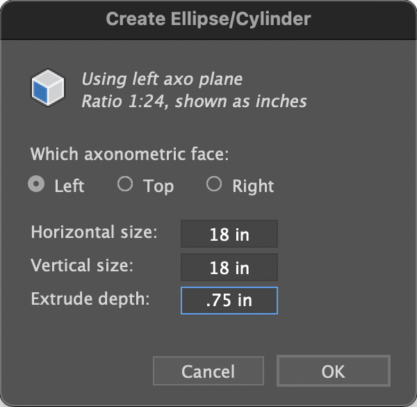
Art created numerically with an Extrude depth is created using AxoTools’ Extrude function, and so will be given strokes and fills according to settings in the Draw Settings panel.
 Art created by dragging the tool or with an Extrude depth of 0 are created as Projected art, and so will have the document’s current stroke and fill unless the Draw Settings option is chosen in the Projection panel. In that case, the art will be given the fill and stroke options in the Draw Settings panel.
Axo Rectangle tool
![]() The Axo Rectangle tool works similar to the Axo Ellipse tool, except that it draws a rectangle. Like the Axo Ellipse tool, pressing the Shift or Alt/Option keys work as they do in Adobe Illustrator’s built-in Ellipse or Rectangle tools, only the art is drawn on an axonometric plane.
The Axo Rectangle tool works similar to the Axo Ellipse tool, except that it draws a rectangle. Like the Axo Ellipse tool, pressing the Shift or Alt/Option keys work as they do in Adobe Illustrator’s built-in Ellipse or Rectangle tools, only the art is drawn on an axonometric plane.
 Create rectangle numerically
Click with the tool to display a dialog box to create a rectangle numerically. Enter a height and width, which will be scaled according to the document scale in your preferences. You can also enter a depth value to extrude the ellipse to create a box. It can be styled according to your Axo Draw settings and preferences settings.
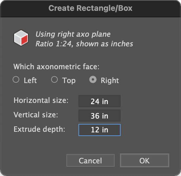
Art created numerically with an Extrude depth is created using AxoTools’ Extrude function, and so will be given strokes and fills according to settings in the Draw Settings panel.
Art created by dragging the tool or with an Extrude depth of 0 are created as Projected art, and so will have the document’s current stroke and fill unless the Draw Settings option is chosen in the Projection panel. In that case, the art will be given the fill and stroke options in the Draw Settings panel.
Axo Scale tool
![]() The Axo Scale tool allows you to scale art within an axonometric plane. It works similar to Adobe Illustrator’s standard Scale tool, but within an axonometric plane.
The Axo Scale tool allows you to scale art within an axonometric plane. It works similar to Adobe Illustrator’s standard Scale tool, but within an axonometric plane.
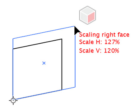 Its default anchor point is the center of the selection, but you can click to define a new anchor point. Press Alt/Option to cycle through the three projection planes. The plugin will display colored lines indicating the two major axis for the current plane. A cube annotation will appear with one of the three faces highlighted, color-coded with the protractor in either red (right), blue (left) or green (top). Press the Shift key while dragging to constrain the scaling to the direction of the protractor lines.
Note: To keep the UI for Axo Scale tool simple and intuitive, it will not scale artwork constrained proportional to the original. To achieve this same result, scale the art with Adobe Illustrator’s standard Scale tool.
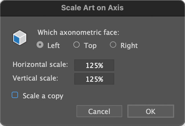
Scale numerically
To scale numerically, Alt/Option click where you want your anchor point, then fill ini the horizontal and vertical scales, then select a face to scale on and click OK.
Axo Rotate tool
![]() The Axo Rotate tool will allow you to rotate artwork within the plane of its axonometric projection. It functions similar to Adobe’s Rotate tool in that its default anchor point is the center of the selection, but you can click to place the anchor anywhere you’d like.
The Axo Rotate tool will allow you to rotate artwork within the plane of its axonometric projection. It functions similar to Adobe’s Rotate tool in that its default anchor point is the center of the selection, but you can click to place the anchor anywhere you’d like.
The plugin will display an axonometric protractor with colored lines every 90° and gray lines every 15°. Press Alt/Option to cycle through the three projection planes. A cube annotation will appear with one of the three faces highlighted, color-coded with the protractor in either red (right), blue (left) or green (top).
 Press the Shift key while dragging to constrain the rotation to increments of 15°.
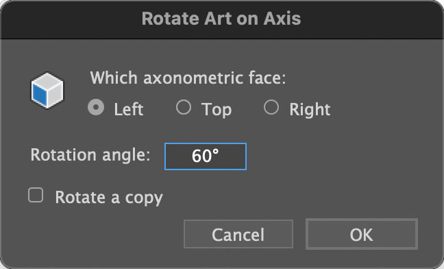
Rotate numerically
To rotate art numerically on a projected plane, Alt/Option click on a location for the anchor point of the rotation. In the dialog box that appears, fill in the rotation amount and the face upon which to rotate.
Axo Shear tool
![]() The Axo Shear tool will allow you to shear artwork within the plane of its axonometric projection. It functions similar to Adobe’s Shear tool in that its default anchor point is the center of the selection, but you can click to place the anchor anywhere you’d like.
The Axo Shear tool will allow you to shear artwork within the plane of its axonometric projection. It functions similar to Adobe’s Shear tool in that its default anchor point is the center of the selection, but you can click to place the anchor anywhere you’d like.

The plugin will display a cube annotation with one of the three faces highlighted, color-coded with the protractor in either red (right), blue (left) or green (top). The chosen axonometric plane’s X and Y axis will be shown.
 Press the Shift key while dragging to constrain the shear to increments of 15°.
Shear numerically
To shear art numerically on a projected plane, Alt/Option click on a location for the anchor point of the operation. In the dialog box that appears, fill in the shear amount, the axis angle to shear on, and the face upon which to shear.
Axo Extrude tool
![]() The Axo Extrude tool extrudes a path along an axonometric axis. To use it, select a path or compound path and do one of the following:
The Axo Extrude tool extrudes a path along an axonometric axis. To use it, select a path or compound path and do one of the following:
- Drag along an axonometric axis.
- To project orthographic art into an axonometric orientation before extruding it, press and hold the Alt/Option key as you drag.
- Click without dragging to extrude other selected artwork along the same axis, same distance, and same projection setting as the last extrude operation.
- Click and drag in an orthographic view (when reference points are enabled) as described below.
Extrude by reference from an orthographic view
When you extrude selected, projected art in an axonometric view, you can specify the depth of the extrusion by dragging an equivalent distance in one of your orthographic views. For example:
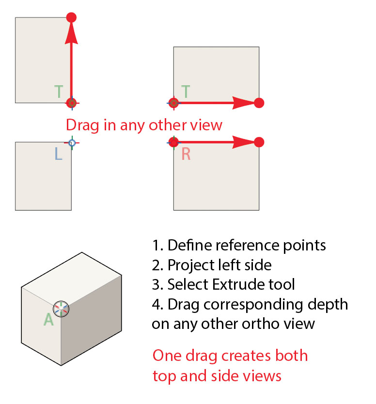
The distance will be foreshortened for the angle of the axis and the direction will correspond with the direction you drag in the ortho view.
Stroke and fill options
When extruding, you have a number of options for how the art ic created, which are selected in the AxoTools Draw Settings panel found in the menu at Window > AxoTools > AxoTools Draw Settings.
There are four fill options. Wireframe simply extrudes the art with no fills. Fill with white creates panels for each face filled with white. A third option uses the art’s current stroke and fill colors. Shaded object color starts with the path’s fill color (or adds a light gray fill if the art is not filled already) as the color for the left face. The top face is tinted lighter and the right face is darkened to simulate an upper-left light source.
Hidden faces can be included in your extruded art or omitted for simplicity.
Strokes can be added to the art using predefined thick and thin widths using the “air-behind” method. When using this option, the filled panels will have no stroke. Stroke widths can be entered in any units supported by Illustrator’s many fields, such as “in” or “pt” or “mm.”
The option to automatically concatenate lines applies to the Axo Line tool described earlier.
Enter other ruler units
The distance to extrude is shown in the current document’s ruler units, but you can enter a different measurement if you wish, and it will be converted to the default unit. For example, if your document uses points, you can enter “1 mm” and it will be converted to the equivalent of 2.835 points.
Extrude at free-form angles
Press Cmd/Ctl after you start dragging with the tool to extrude and project along a free-form angle. Keep the Cmd/Ctl key down as you release the mouse.
Extrude numerically
To extrude path art numerically, use the AxoTools Extrude panel.
Axo Measure tool
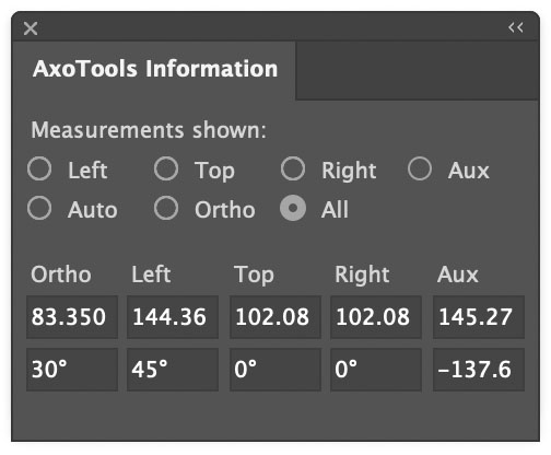
![]() The Measure tool allows you to measure distances and angles in any of the three axonometric axes, scaled for the foreshortening factor of that plane as well as the direction of the measurement within that plane. Measurements are displayed for all axo planes as well as orthographic, and distances along the auxiliary depth axis.
The Measure tool allows you to measure distances and angles in any of the three axonometric axes, scaled for the foreshortening factor of that plane as well as the direction of the measurement within that plane. Measurements are displayed for all axo planes as well as orthographic, and distances along the auxiliary depth axis.
 Information panel
In the Information panel, choose a set of measurements to display, choose “Auto” to let the tool guess what you’re measuring based on the direction you drag the mouse, or choose “All” to see results for all planes.
Drag to measure distance and angle
To use the tool, simply click and drag to measure a distance and an angle.
Measure arc between two angles
To measure the angle between two intersecting lines on an axonometric plane, click at their intersection, then drag an arc from one of the lines to the other.
Constraining the measurement angle
Press Shift to constrain to the nearest 45°, or press Alt/Option if you’d like the tool constrained along your current axonometric axes.
Auto-enter measurements into panel fields
You can automatically enter values from the orthographic measurements into the Extrude panel’s Distance or Angle fields, the Projection panel’s X or Z axis fields, or the Transformations panel Extrude distance field, just double-click the field’s label. To enter values into the Transformation’s Move/Rotate field, simply press “d” or “a” for “distance” or “angle” as applicable.
Axo Fastener tool
![]() TheAxo Fastener tool allows you to quickly create fasteners along any axonometric axis, using the fasteners and options chosen on the Fasteners panel.
TheAxo Fastener tool allows you to quickly create fasteners along any axonometric axis, using the fasteners and options chosen on the Fasteners panel.
- Click to create the fasteners at the location you choose.
- Click and drag to draw the fasteners, constrained along the closest axis.
- Press Shift as you drag to reverse the order and direction of the fasteners.
- Press Alt/Option as you drag to force the fasten(s) to be drawn as seated.
- Alt/Option click on an existing fastener to import its properties into the Fastener panel.
Note: Built-in fasteners will be automatically reversed as needed to conform to the direction of its axis. Symbol-based fasteners will retain their orientation as drawn. That is, they will not be automatically drawn reversed.

Axo Zone tool
![]() The Axo Zone tool allows you to define zones for the boundaries of your left, right, top, bottom, and axonometric views. These zones are not necessary to use any of the tools, but can be helpful at times, depending on the layout of your different views.
The Axo Zone tool allows you to define zones for the boundaries of your left, right, top, bottom, and axonometric views. These zones are not necessary to use any of the tools, but can be helpful at times, depending on the layout of your different views.
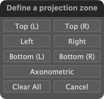
When a view is defined and the Zone tool is active, zones are displayed with a gray box. A label above it identifies which zone it is.
If the Common Reference Point for that view is not yet defined to lies outside of the zone that defines the view’s boundaries, the Common Reference Point will be moved to the center of the zone.
When you hover your mouse over a zone, it will be highlighted with handles to adjust its size. Pressing the mouse button while in the interior of the zone, you will see a hand cursor, indicating that you can move the zone.
Click and drag in any of the zone’s handles to resize it.
Press Alt or Option, then click within the zone to reposition its Common Reference Point.
Zone usage example
Axo Axis tool
![]() The Axo Axis tool is used to adjust the Z axis of projected art when using the Auxiliary Projection panel. It is not used at any other time, so please see Step 6 of that section for information on this tool
The Axo Axis tool is used to adjust the Z axis of projected art when using the Auxiliary Projection panel. It is not used at any other time, so please see Step 6 of that section for information on this tool