AxoTools adds “bottom” projection support
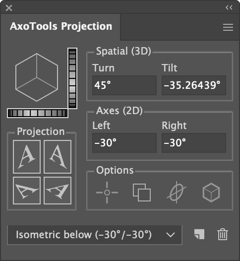 If you adjust the Tilt value of your projections using the dial control to the right of the proxy cube image, you’ve possibly found that it now allows you to tilt far enough to show the bottom of the cube. You could also just enter negative values for the left and right axes, or a negative Tilt value.
When that happens, the projection buttons change their orientation to make sense for the inverted view, including moving the “top” buttons to below the sides for “bottom” projections.
The left and right axes will now both show as negative values.
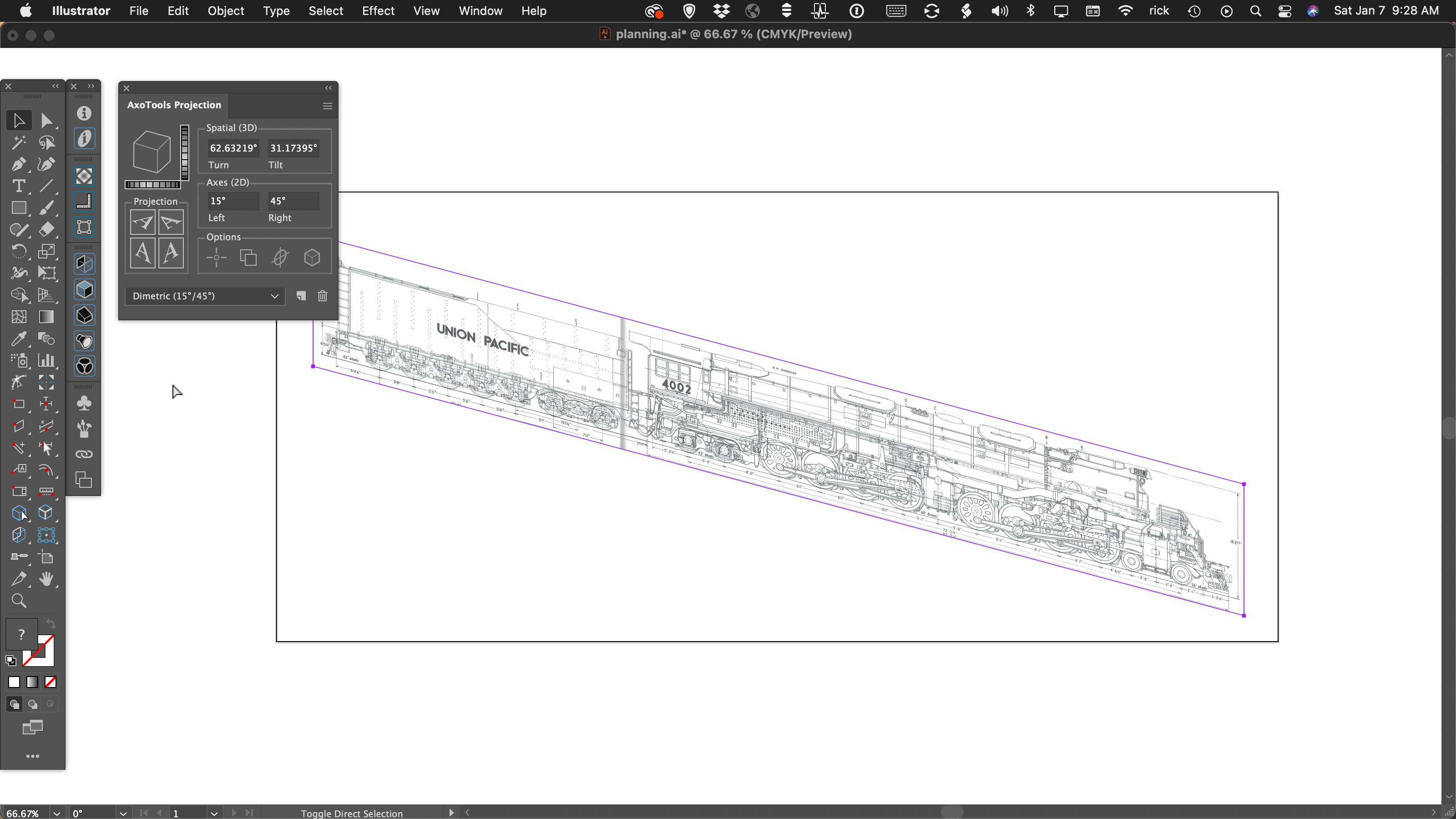
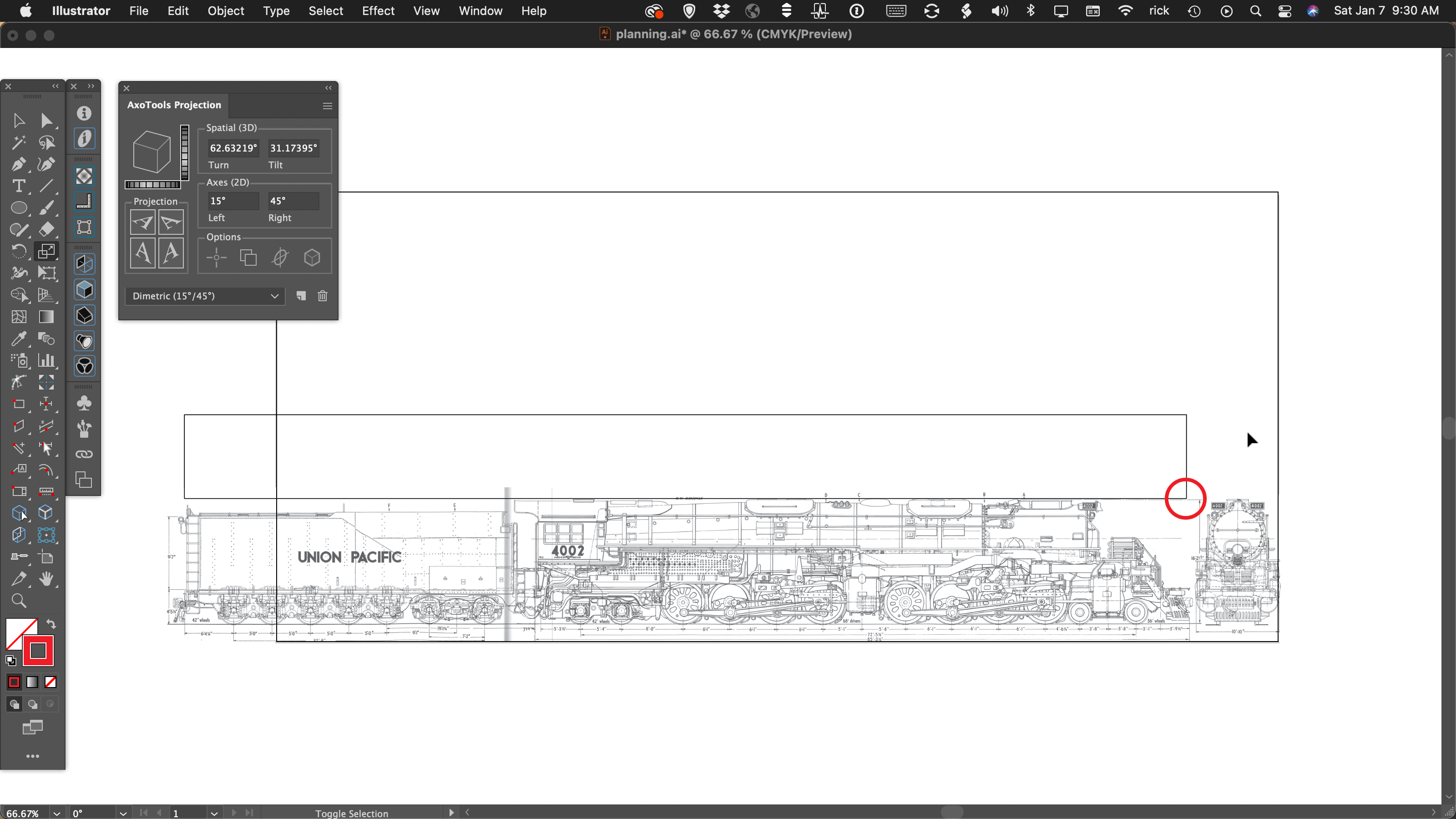
In this example, how many of you had one of these in your living room growing up? Stereo consoles were quite the rage in 1970, but were replaced with component-style equipment not long afterward. It provides a good example of an underside view, to show the location of the four feet.
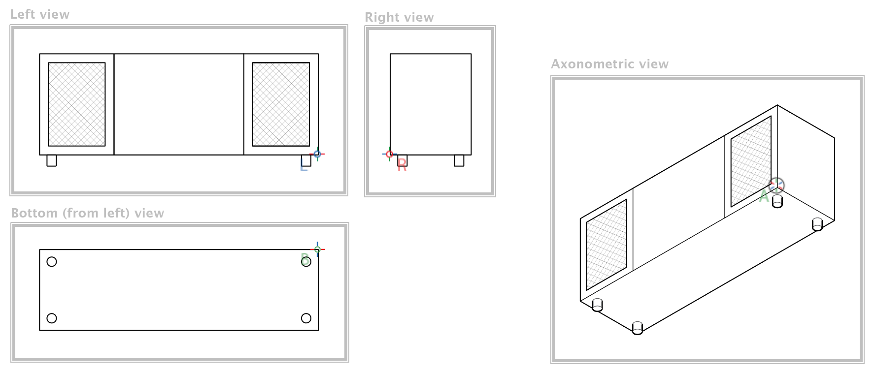
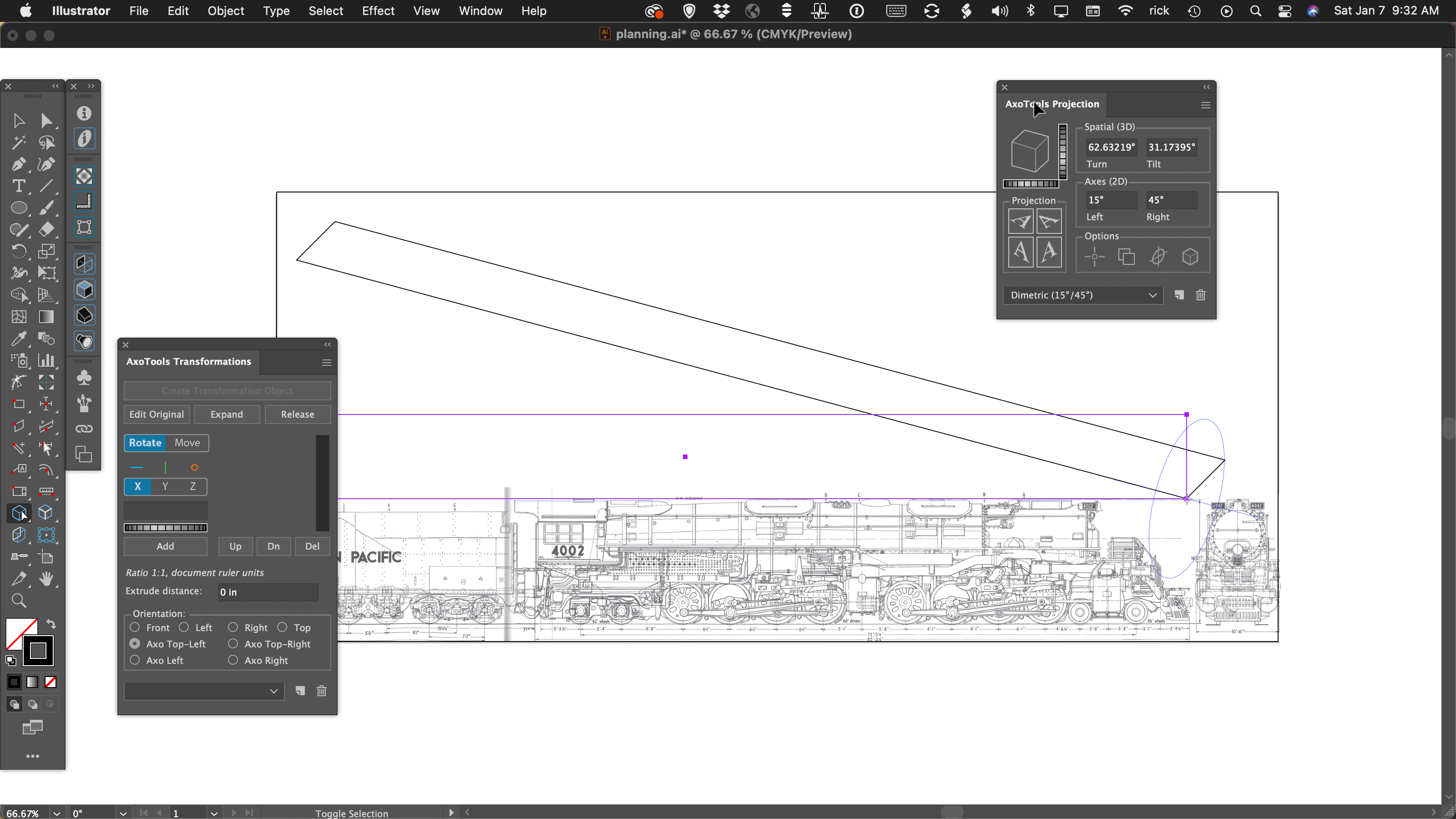
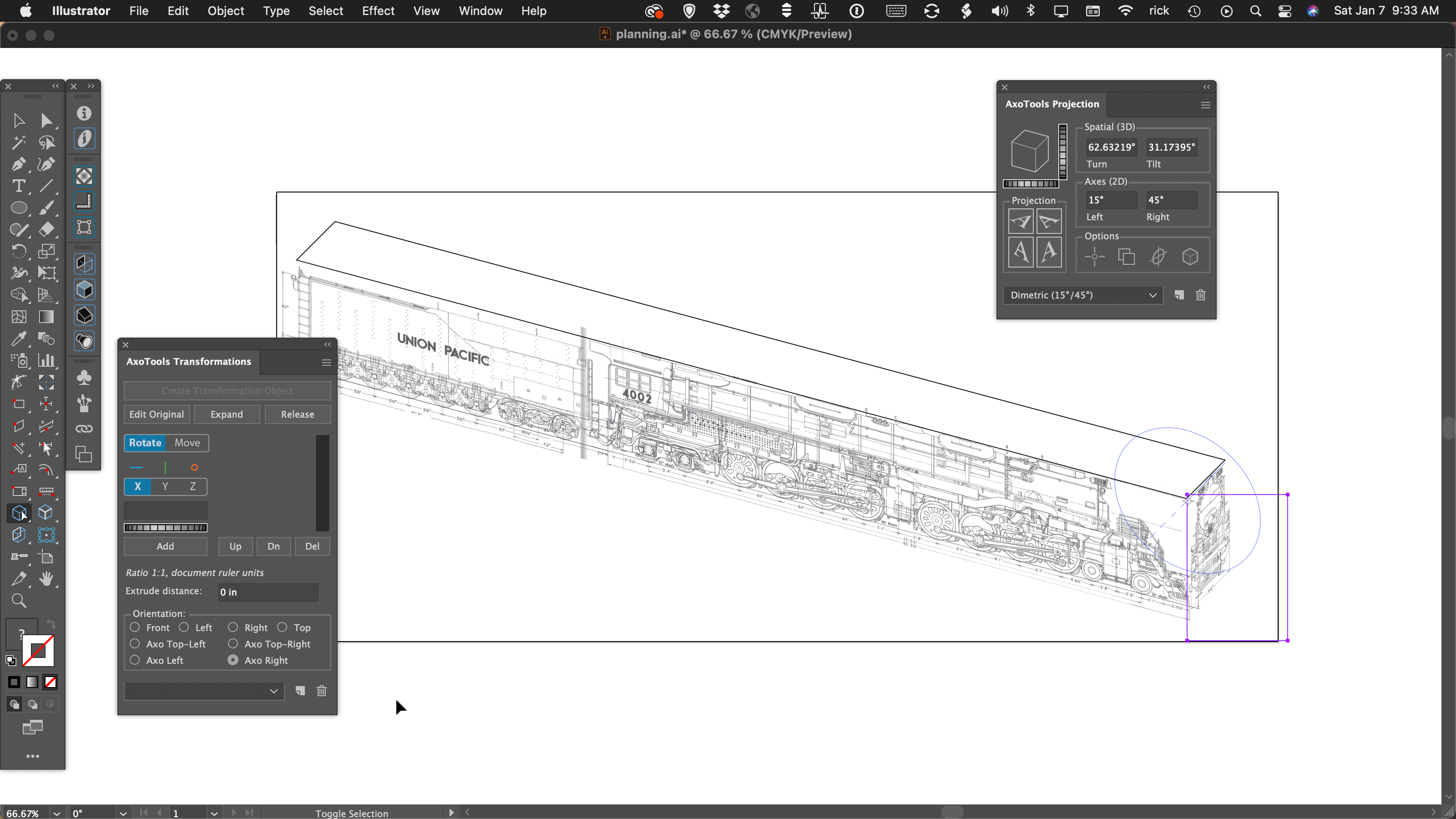
In this case, I’ve defined the four zones, which now need to include options for bottom-left and bottom-right zones, as well as bottom reference points. In most cases, you really won’t need to define zones, but if you have large or complex ortho views that you move or extrude by reference, it can save you from some unexpected behavior later.
While revising the Zone tool and zone creation, it seemed a good time to make other improvements to the Zone tool and its functions to make the process easier and more intuitive. Reference points are now visible while the Zone tool is active, and they can be created here now, as well. Rather than draw a rectangle every time, you now have the option of selecting art from an ortho view, and the tool will draw a rectangle to enclose it. Other details are available in the updated documentation for the tool.
To summarize, the Projection panel now supports Tilt and Turn values that show many combinations of the left and right planes, plus the top or bottom.
Now, this may be going kind of crazy, but it would be possible to add the option to project art to a back surface. This might look like a sign painted on a window, but appearing backward as viewed from inside the building. Would that be useful?
![]()
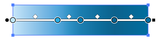
 Using a single line weight (or “stroke width” as it applies to Illustrator’s path art property) is a simple and efficient way to work.
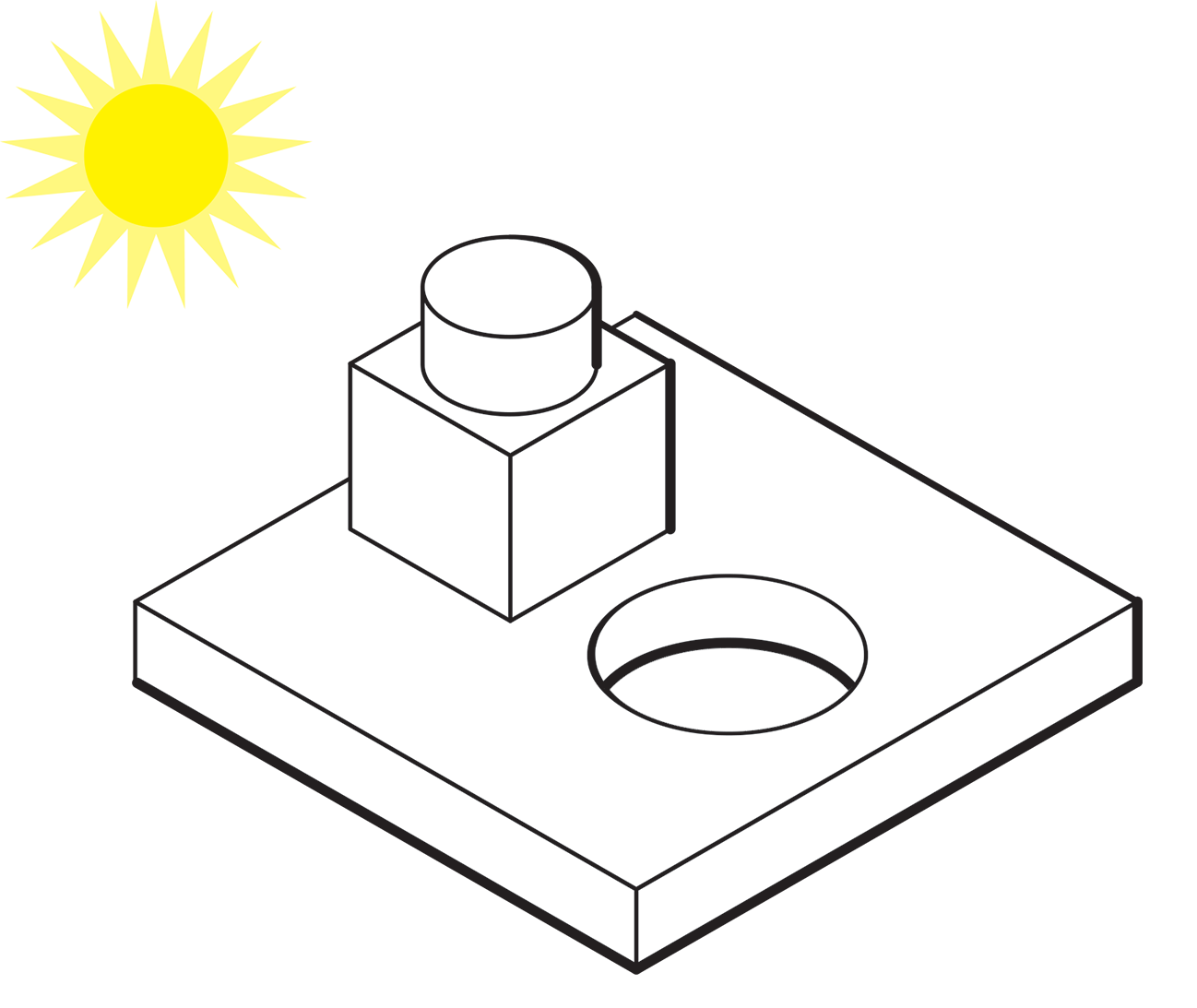
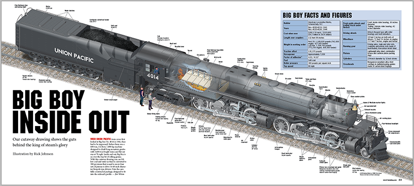
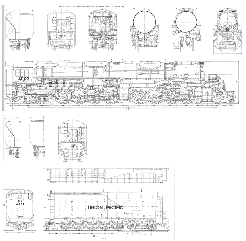
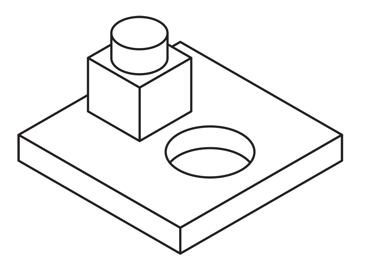
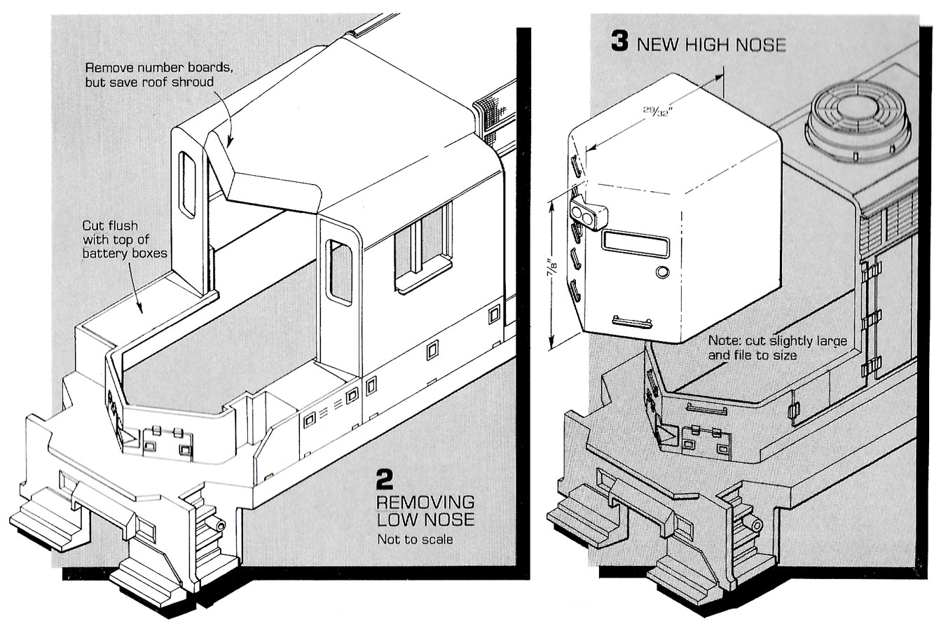 Here’s an example of an illustration I did using the “Kalmbach” method, drawn in ink at 1.5 times reproduction size. Detail lines were drawn with a 4×0 Rapidograph pen, and the heavy lines were probably a no. 0 or 1 pen. In those days, we typically cut an Amberlith overlay to add a flat tint to the background, which helped separate the subject from the background.
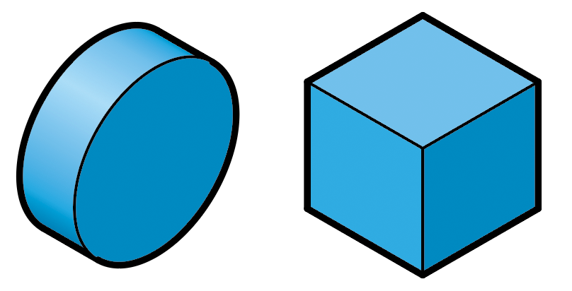
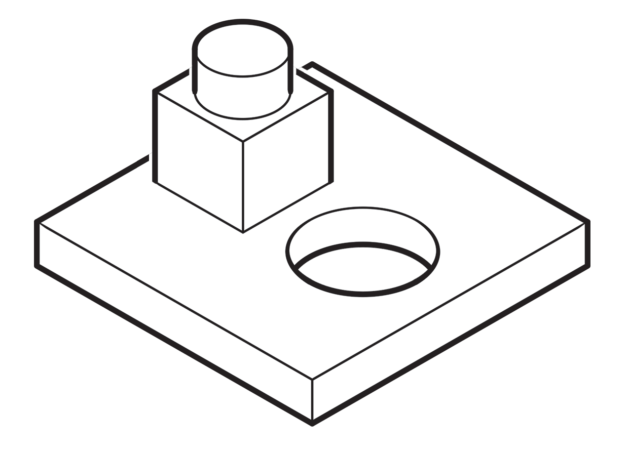 A more common method called “line contrast shading” used in exploded-view parts drawings uses heavier lines on all outside edges of objects. In this example, the bottom of the cube and cylinder are thin lines because they represent the joint between two surfaces. A heavy line would suggest the objects float above the other art. In the case of the round hole, a varied line width makes a smooth transition between the front- and rear-facing edges. Complex illustrations can use three or four line weights. Standards are more like guidelines, actually, that vary between people and between businesses, often based largely on the personal preference of someone with experience and/or influence.
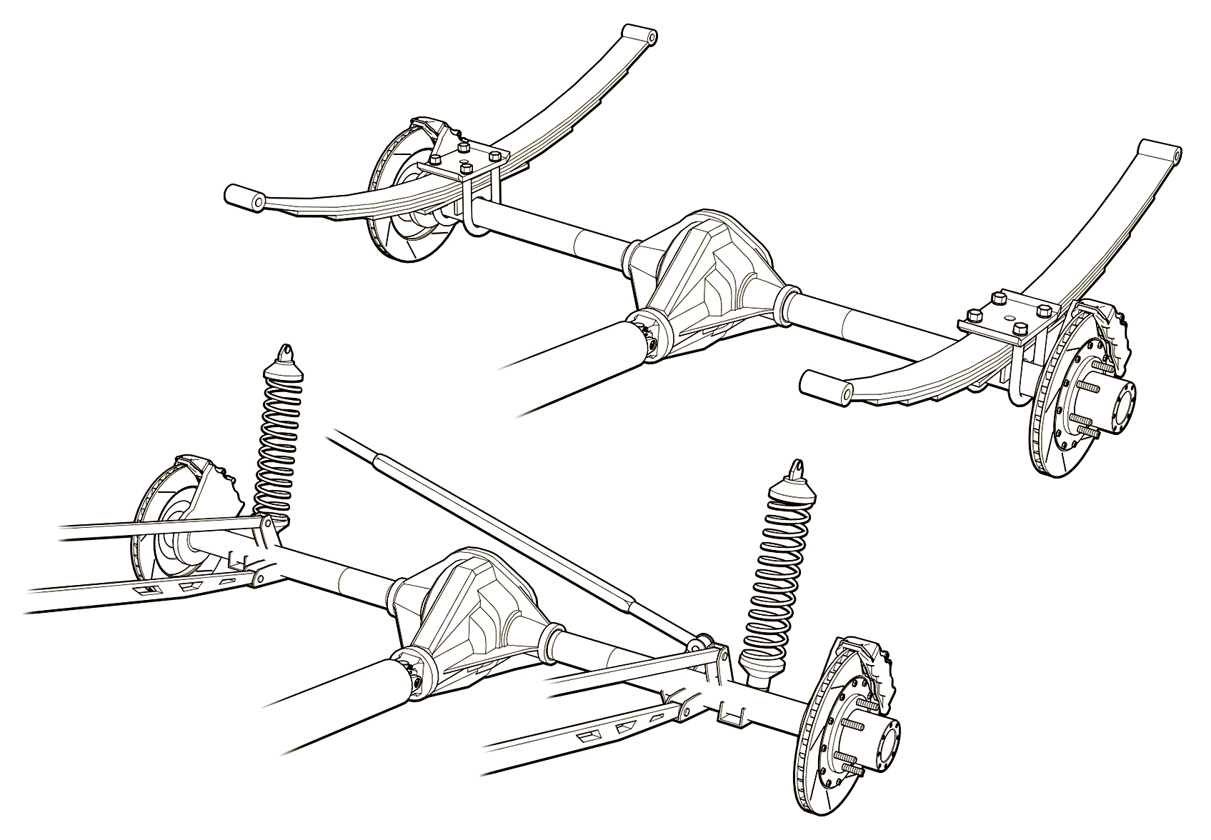 Greg used a three weight treatment on this Raptor suspension illustrations for Car and Driver magazine.
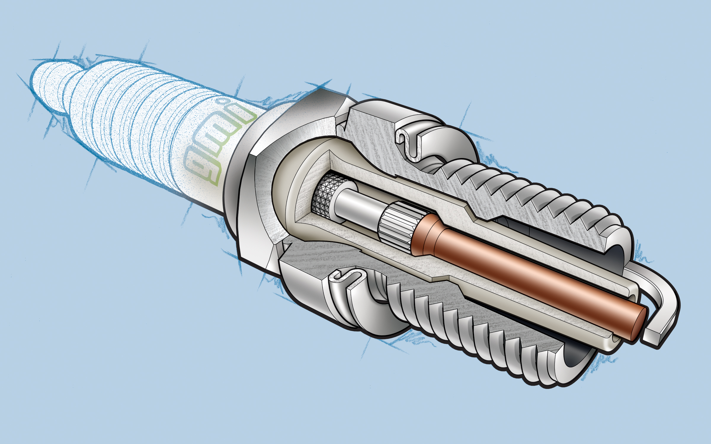 One more piece by Greg Maxson shows his skill at technical illustration using a variety of software, often including SketchUp, Illustrator, and others. Here he adds clarity to the subject with varied line weights, line colors, sometimes sketchy line treatments, and meaningful shading and textures in filled areas.
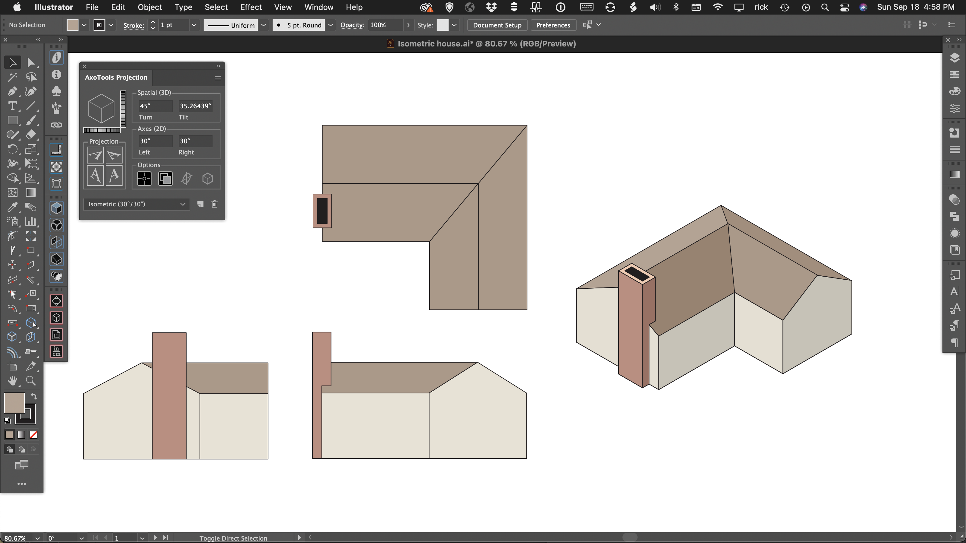
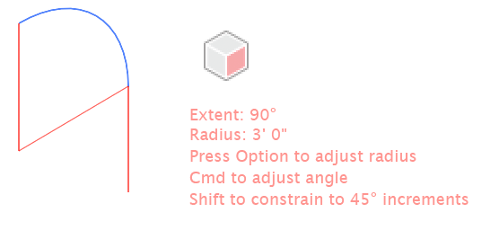 As you drag with the Axo Arc tool, the arc will appear highlighted. You can drag the arc forward or backward, left or right. Guide lines will appear to show the location of the arc center as well as a tangent line of the arc’s exit angle. If your preferences select Help text, the tool will also display the current arc’s extent angle and radius.
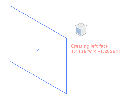
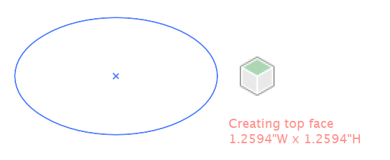 As you drag with the Axo Ellipse tool, the ellipse will appear projected onto your current axonometric plane. If your preferences select Help text, the tool will also display the current width and height using the units specified in your preferences and scaled to your document scale.
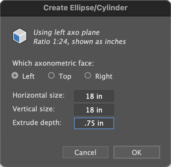
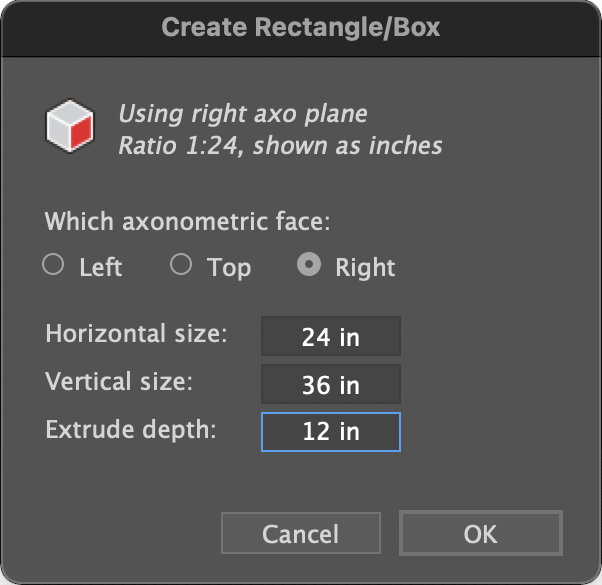
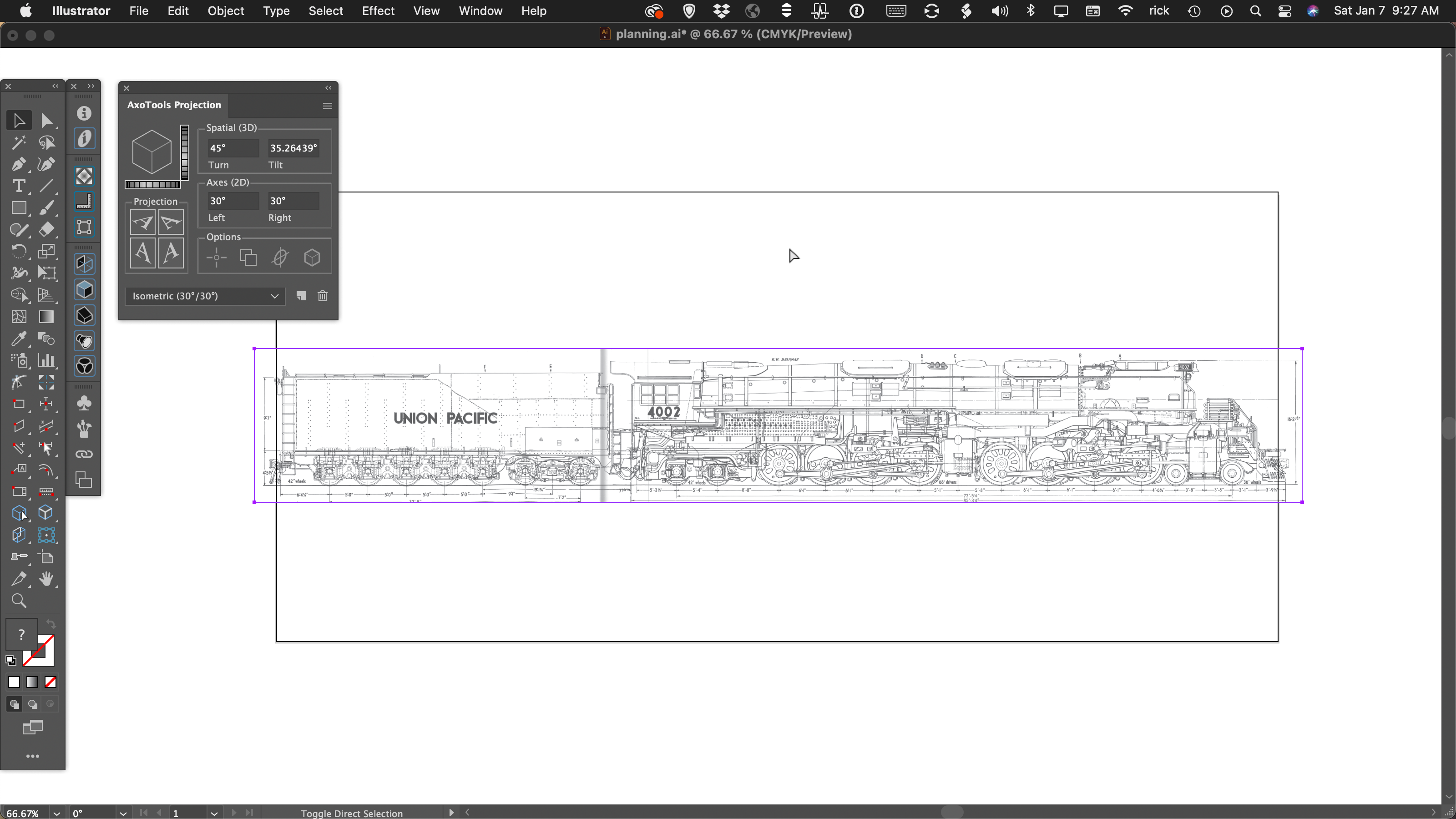
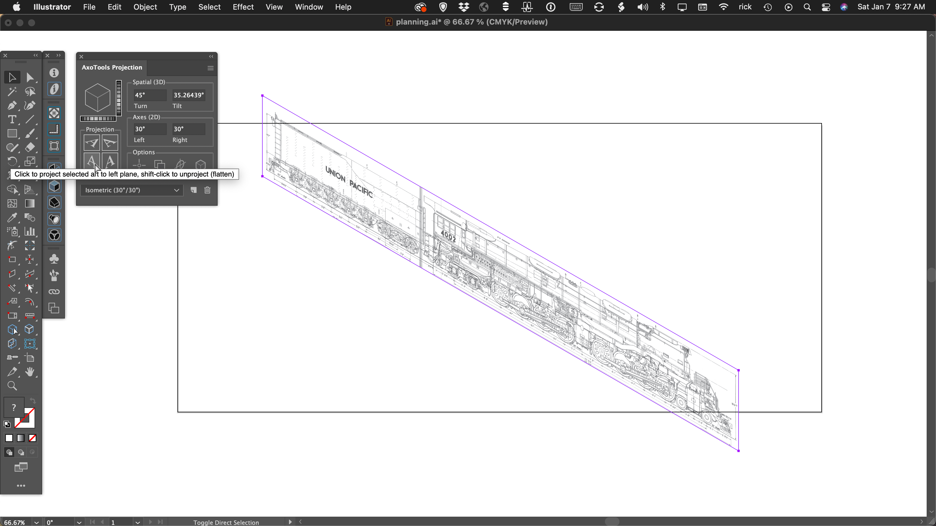
 The Axo Rectangle tool works similar to the Axo Ellipse tool, except that it draws a rectangle. Like the Axo Ellipse tool, pressing the Shift or Alt/Option keys work as they do in Adobe Illustrator’s built-in Ellipse or Rectangle tools, only the art is drawn on an axonometric plane.