Perspective panel adds utility functions
AxoTools’ new Perspective grid has added a couple of new utility functions in a flyout menu.
Define 3-pt. grid
 Defining a perspective grid in Adobe Illustrator has long been a bit of a puzzle. Illustrators have an idea of how we want our art oriented, but the fields in Adobe’s Define Perspective Grid dialog seem to have been geared to serve the software, not the user. AxoTools now makes that process a bit easier by offering a sort of visualizer for defining a three-point perspective.
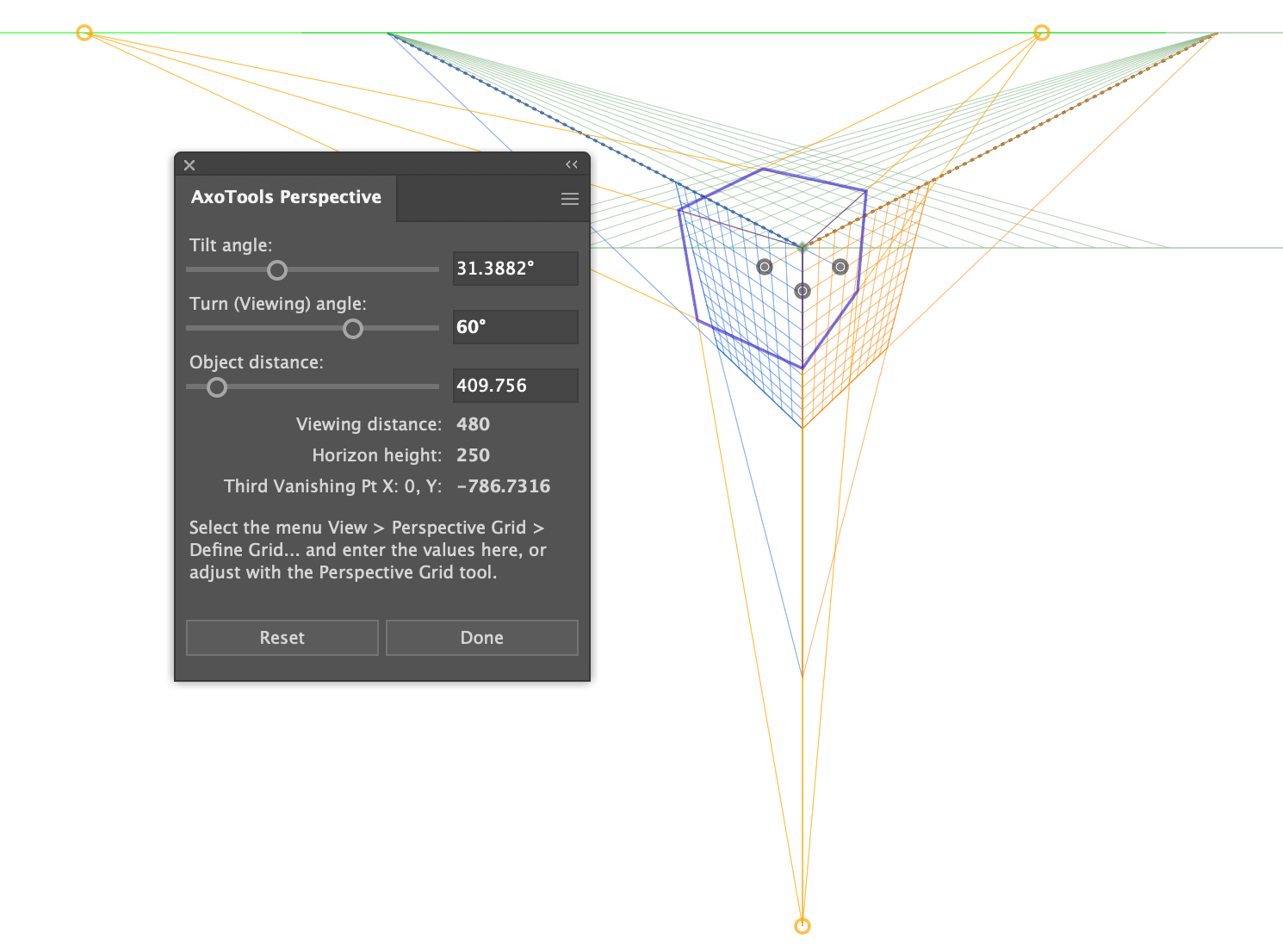
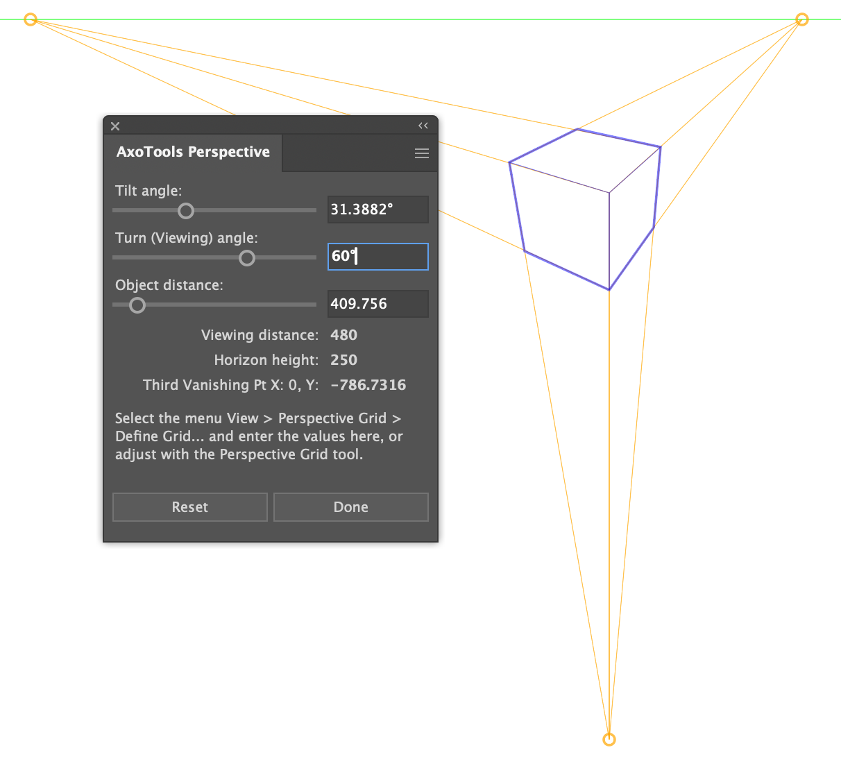
Select “Define 3-pt. grid” from the flyout menu and the Perspective panel changes to show an alternate group of settings. You’re already familiar with the axonometric projection’s Tilt and Turn method of rotating your art, so this utility draws on that method. Rather than drawing a small proxy cube, however, the panel draws the cube and the lines to the vanishing points right on the artboard, aligned with your current perspective grid. You can hide the current grid (Shift-Ctrl/Cmd-I) to see your changes without distractions. Simply drag the sliders to change your top angle, side angle, and wide-angle/telephoto effect.
 One significant advantage here is that AxoTools will calculate a geometrically-correct location for the bottom (third) vanishing point, helping to relieve much of the distortion we see in Illustrator’s perspective art.
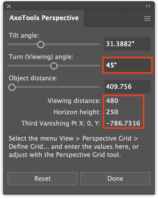
Unfortunately, there is no way for a plugin to make these adjustments to Illustrator’s built-in perspective grid, so you have a couple of options. You can often use the Perspective Grid tool to adjust Illustrator’s grid to approximate the panel’s settings, but the most reliable method is to enter four of the values shown here into the Define Perspective Grid dialog.
You can find more detailed information in the online documentation.
Correct perspective distortion
Adobe’s developer SDK for Illustrator provides third-party plugins access to placing path art on a perspective grid, but adding text or symbols to it are handled by other built-in Adobe plugins. That means they have to be added with Adobe’s native tools, and thus subject to the distortion we get in side planes of three-point grids and all planes of one-point grids. To correct the proportions of those art types, or any art previously added to a perspective grid, simply select the art on the grid, then select this item from the Perspective panel’s flyout menu.
These two functions are FREE and will continue to work after the trial period has expired.
I hope you find them useful and help make Illustrator’s perspective grid easier to use.
![]()


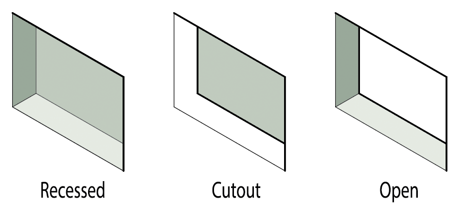 Recessed appears as a depression in a surface, similar to the “debossed” effect in Photoshop. AxoTools draws side walls and a back plane.


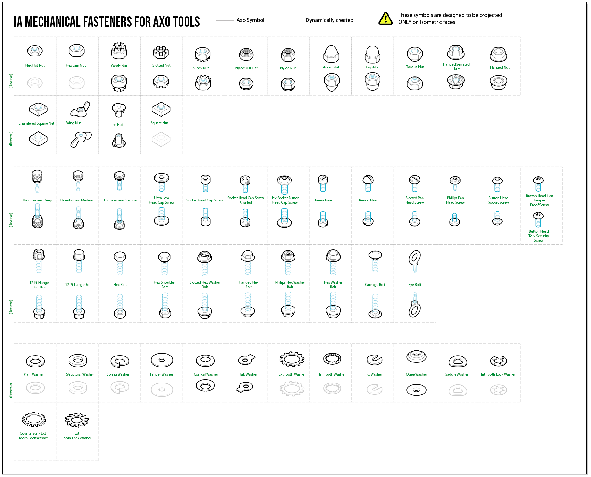
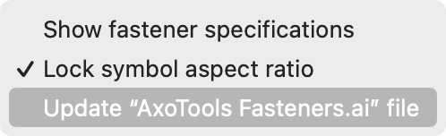
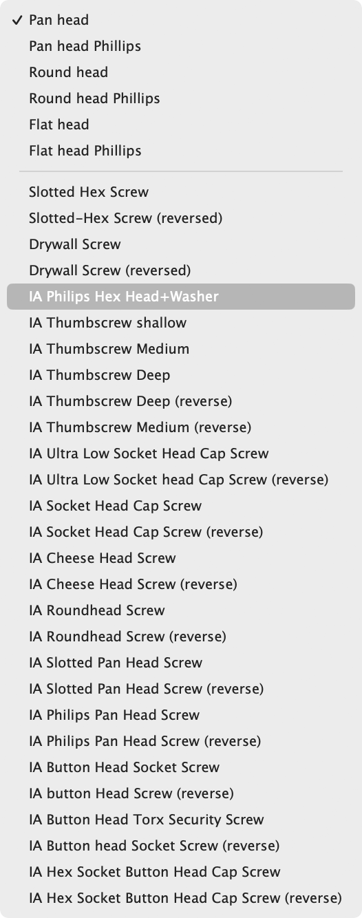
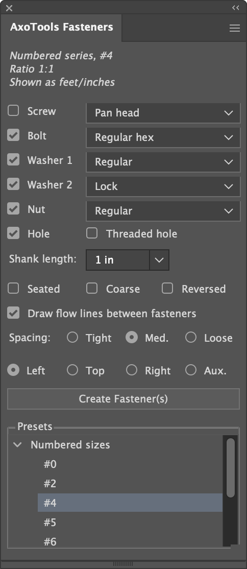
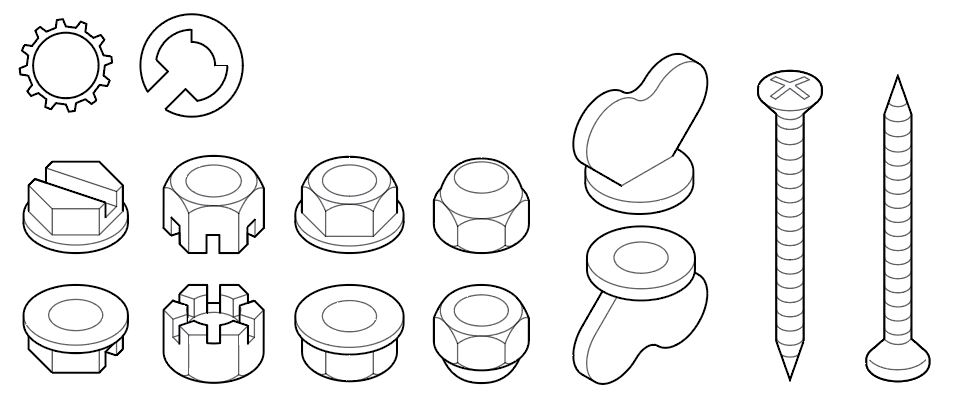
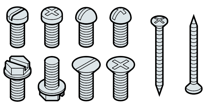 AxoTools has added a new Fasteners panel to help you quickly create fasteners of common types and sizes, scaled to fit your document.