With the latest update to AxoTools, you can enter measurements in whatever units you’re comfortable with. Here’s an example:
Say your document ruler units is set to inches, but you need to extrude something to a distance you have in mm. Illustrator supports that within the app, but it’s not automatically there for plugins. Measurement fields in AxoTools now do that conversion for you. I really hadn’t planned at first on adding that — there’s a back story here.
First, all art in Adobe Illustrator is measured internally in points. Fortunately, Adobe’s interface for plugins includes a function that takes measurements from text typed by the user in the current ruler units and converts it to a numeric value calculated as points. Then another function converts numeric point values used within the plugin to text that plugins can give back to the user, calculated and formatted using their current ruler units. That’s great, but there are a lot of users in other parts of the world that use a comma as a decimal separator. Fortunately, Adobe added a variation of these functions that support international number formats. Unfortunately, the one that parses text with commas in decimals doesn’t see the commas, and the values get multiplied by ten, a hundred, or a thousand! Adobe’s bug became my bug.
To support my European customers, I wrote a function that parses the numbers typed, and honors commas as decimal separators, and wondered “Why not look at the units specified, as well?” All values need to be converted to points anyway for the plugin to work with, so it wasn’t a great leap code-wise.
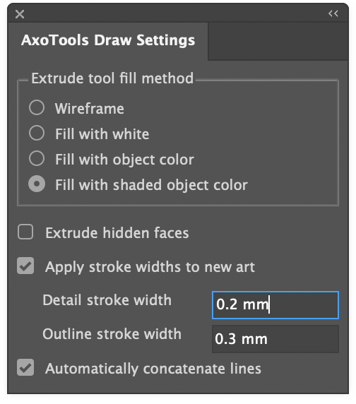
As an extension of that, I wrote a function to convert values back to text with a caveat of my own. In AxoTools’ Draw Settings panel, users can specify standard stroke weights, but we don’t all use points for strokes — many use mm. Stroke measurements have little to do with our current ruler units, so the plugin lets you specify pt or mm, does the math when needed, then remembers your preference to always display it your way.
It can be frustrating dealing with bugs, but sometimes bugs can become butterflies!
If you do much freehand drawing with the pencil tool, I’m sure you’ll appreciate the Illustrator 25.3 update with the new canvas rotation feature. In preliminary testing, most Graffix plugins seem to work fine, with one notable exception.
In AxoTools under macOS Mojave, some panel controls such as dials, the Projection panel’s proxy cube, and the list in the Transformations panel appear blank. I’ll address these as soon as possible, but it will likely have to wait an update to the CORE libraries these plugins are based on. If this affects you, you may want to either update your OS or hold off on updating to AI 25.3, or also keep a second older version of Illustrator on your hard drive for when you need to use those AxoTools controls.
Compatibility with Apple’s new M1 processors is also expected in a new CORE update, but no availability date is available.
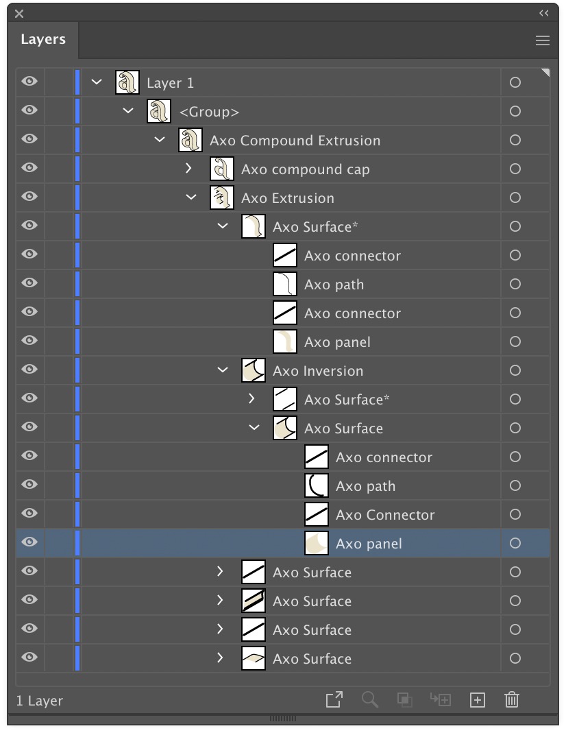
AxoTools is not a 3D application, but tries to assist illustrators in achieving a 3D look the best it can. Simple shapes are pretty straightforward, but complicated shapes can wind over and under each other like an Escher drawing. In that case, AxoTools evaluates the paths and makes its best guess on correctly stacking the pieces.
When a path is extruded, AxoTools creates closed paths for fillable areas and open paths of multiple stroke weights. To make things more easily edited, the pieces are organized into groups. In the Layers panel, you can expand these groups to find the pieces you may want to edit. Compound paths contain elements nested inside of other elements, so things get a bit more complex.
The front surface is named as a “cap,” and is placed above all of the edge pieces. The edges, which give it depth, are divided into surfaces. Each surface is composed of fillable “panels,” stroked “paths” that follow the original path’s shape, and “connector” pieces for corners that connect the front cap to the rear cap (the rear cap and hidden surfaces may or may not be drawn depending on your Extrude panel settings).
Update: now with AxoTools 16.2, there’s an easier way!
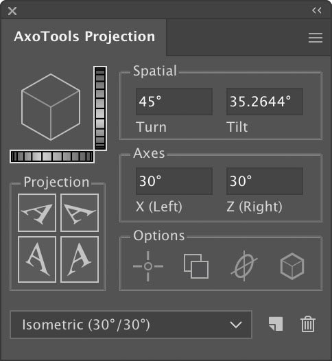
Ron Kempke, who wrote the math behind AxoTools, has provided a follow-up to this post on using an auxiliary view in AxoTools, with these steps on taking it a step farther. Even with the oblique plane rotated at all three axes, we can still construct an auxiliary view and establish an axis for extruded art on that plane.
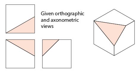
In this example, we have a simple cube with one corner removed. With the three sides projected, the triangle shape practically draws itself, but a problem arises when other objects need to be added that match this orientation.
Here, Ron walks us through this process using the AxoTools Projection panel along with Illustrator’s built-in Scale and Rotate tools.
To start, we need to do some construction drawing in the orthographic top view. You’ll probably want to work on copies of these views. Select the long side (hypotenuse) of the triangular shape in the top view. Copy and paste it, then rotate it 90°. Position this line to divide the shaded triangle at its right-angle corner at the corner of the cube. Use this as a guide to draw the red guide triangle.
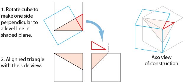
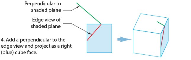
Align the right angle of this triangle with the upper left corner of the right side view. Rotate the top view to match the guide triangle, as shown in the blue square below, then project this to the axonometric top view.
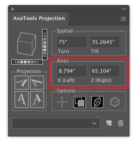
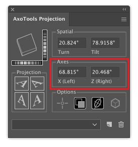
Use Illustrator’s Measure tool to measure the angles of this projected shape. Enter these values into the Axis fields of the Projection panel, which will then become a new (but temporary) axonometric view. The top face of the preview proxy cube in the Projection panel should resemble the rotated cube in your art. Note that these values are for this example only; your angles will certainly be different. If you now project the left and right ortho views, it should resemble the blue cube shown above.
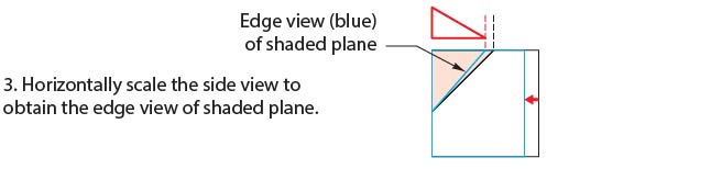
Select the right orthographic view and scale it so that the shaded triangle matches the width of the red guide triangle.
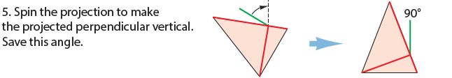
Now on this foreshortened right side view, rotate a copy of the angled line -90° as shown. Here it’s colored green to distinguish it from red guide lines. Remember that having entered new values into the Projection panel axis fields, your projection now matches the blue cube shown below. Project the new guides into your axo view.
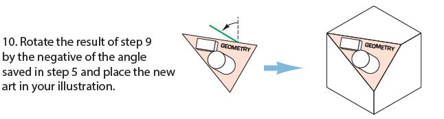
Measure the angle of the green guide line that represents the perpendicular, and save that value for later. Rotate the oblique surface and red guide lines so that the perpendicular is perfectly vertical.
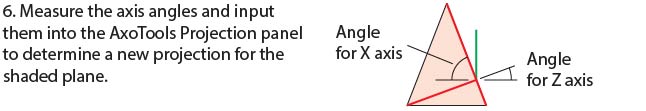
If you’ve entered the new X and Z axis angles correctly, the top surface of the preview cube will be oriented at the same angles as your red guide lines.
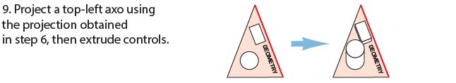
You now have an orthographic (top-left) view of your oblique surface! Add your additional details. It’s worth noting that the red guide line at the top corresponds to the upper edge of the surface on the top view.
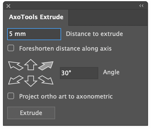
Now extrude any objects on this surface, along the vertical axis. You can do so visually with the Extrude tool, or numerically with the Extrude panel (be sure to check the Foreshorten option). If you have a left or right view showing the depth of the objects on this view and you’ve placed reference points for these views, you can drag by reference in the side view and the depth will be measured and foreshortened for you. (If you extrude a shape on this surface numerically from the Extrude panel, you should be aware that normally objects at this angle recede, so you’ll have to rotate it 180°.)
If you’re using reference points here, remember to redefine them in your standard ortho views when you’re finished with these details.
Finally, set your projection back to isometric or whatever projection your overall illustration used.
In review, the basic steps are:
Find the plane’s perpendicular from the top view.
Define a projection along the top perpendicular to find the plane’s side perpendicular, which is also its extrusion axis, from a side view.
Spin the oblique surface so that its extrusion axis becomes vertical.
Define another projection based on the rotated guides and un-project the oblique surface.
You now have an ortho view of your oblique surface that you can add details to, and save for future reference.
Project a top-left axo view and extrude any objects on that surface.
Spin the oblique surface back to its original orientation.
Many thanks to Ron Kempke for this useful and fascinating exercise!
 AxoTools is not a 3D application, but tries to assist illustrators in achieving a 3D look the best it can. Simple shapes are pretty straightforward, but complicated shapes can wind over and under each other like an