Planning an axonometric projection to fit your space
Sometimes we need to create a projected drawing to fit a particular space. Many of us know the sinking feeling of finding too late that our usual projection (think isometric) just doesn’t fit, and we either live with an orientation that looks like a mistake or we start over. Fortunately AxoTools makes it easy to find out ahead of time what projection is likely to work for us.
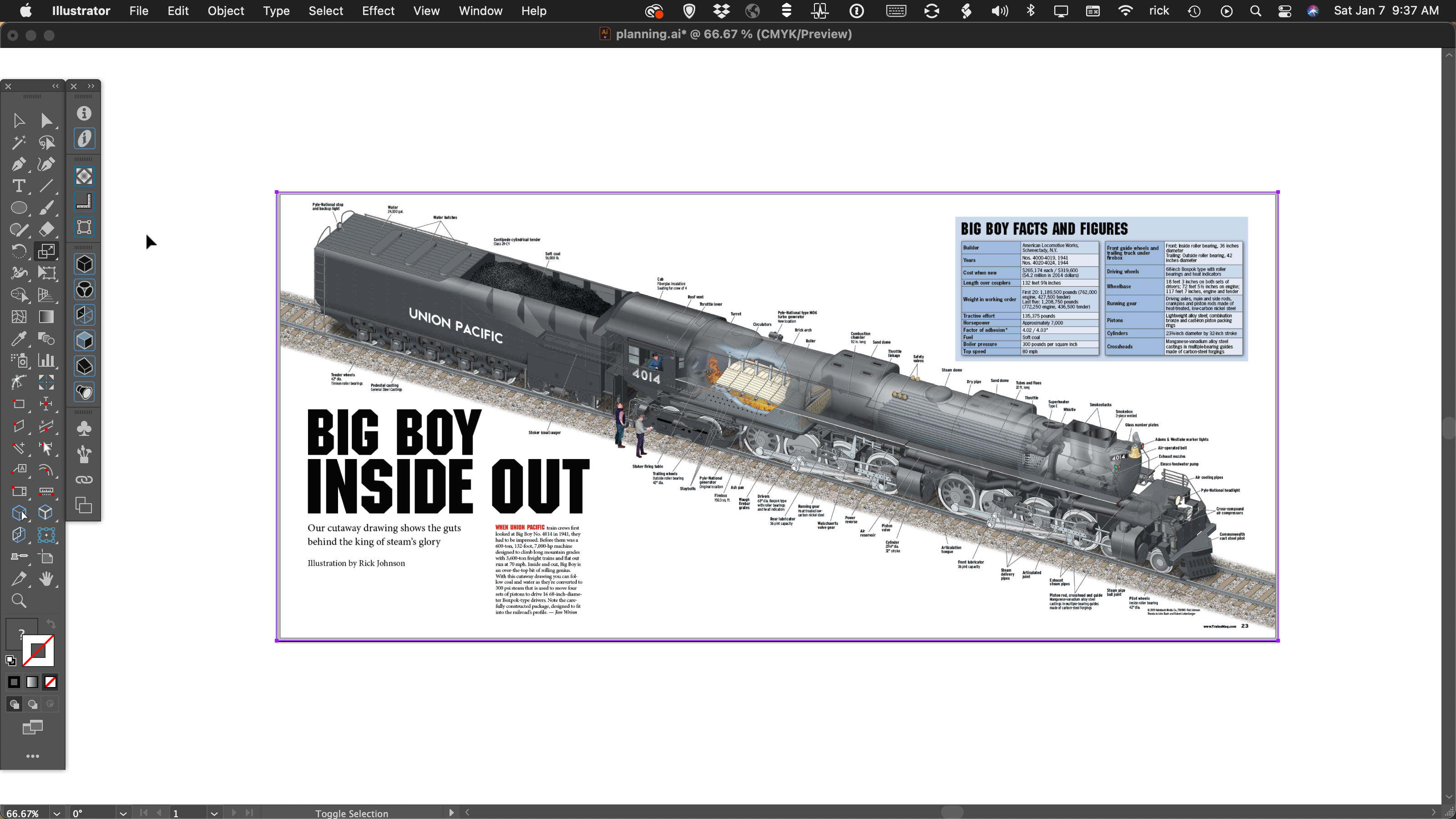
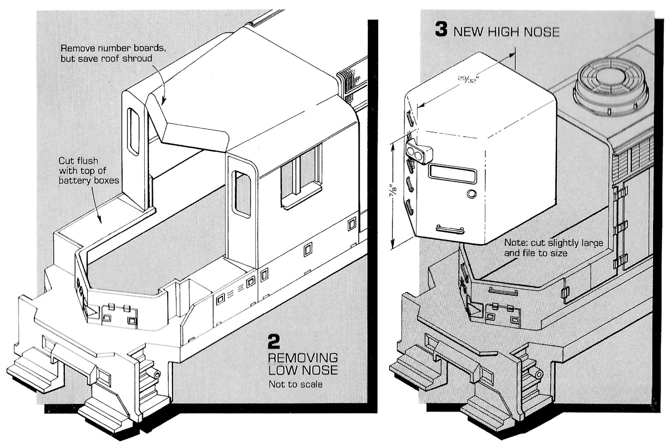
An example of dodging that bullet is a cutaway drawing of a steam locomotive I did for Trains magazine’s special publication on Union Pacific’s newly-restored “Big Boy” locomotive no. 4014.
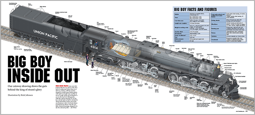
It had to fit into a 3-page foldout, 24.5×11 inches, with room for a headline on the left side and additional information somewhere on the right. I immediately imagined the head in the upper left, with the locomotive facing the lower-left corner. Oh oh. The only detailed reference drawings we had, from the company’s Steam Locomotive Cyclopedia, showed the right side of the locomotive. The two sides are a bit different, so we can’t just reflect it.
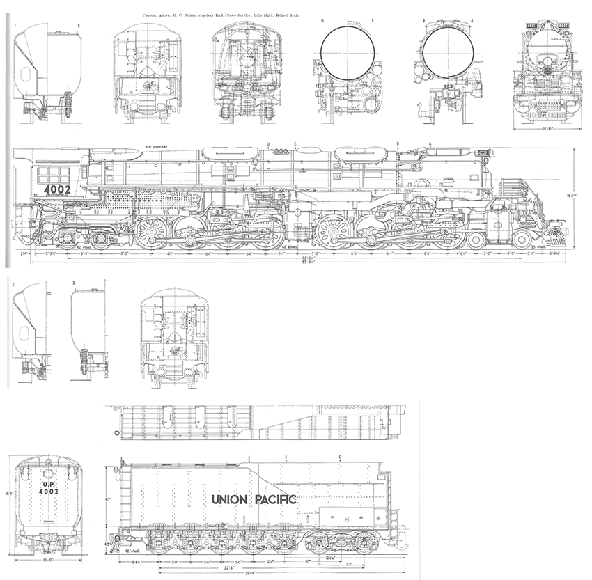
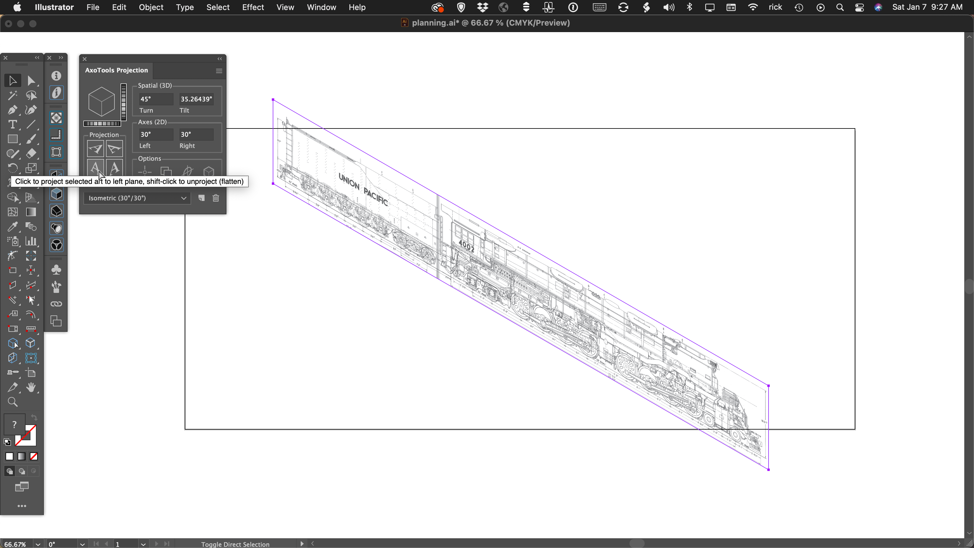
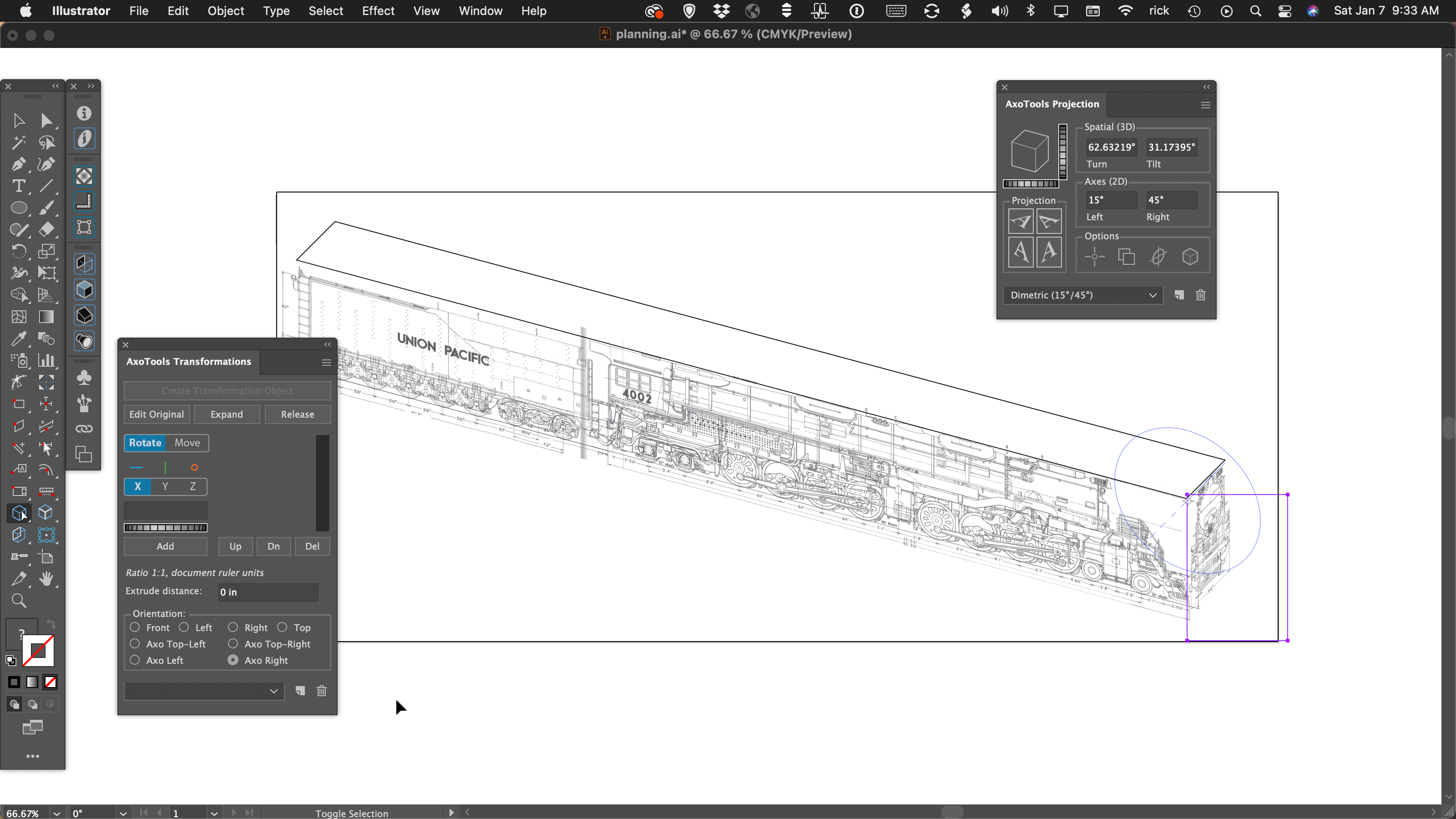
This locomotive is a monster, so I couldn’t risk going too far down the wrong road. In addition to the company’s own previously-published scale drawings, they had some detailed shop drawings from the Union Pacific Railroad itself, so there were strong advantages to drawing it to a real scale (with CADtools) rather than just stretching one reference drawing to fit. Since any axonometric drawing will be foreshortened to some extent, I tried a scale of 3/16″ = 1 foot. For the sake of planning, I placed a rough scanned image in the artboard, then tried various projections.
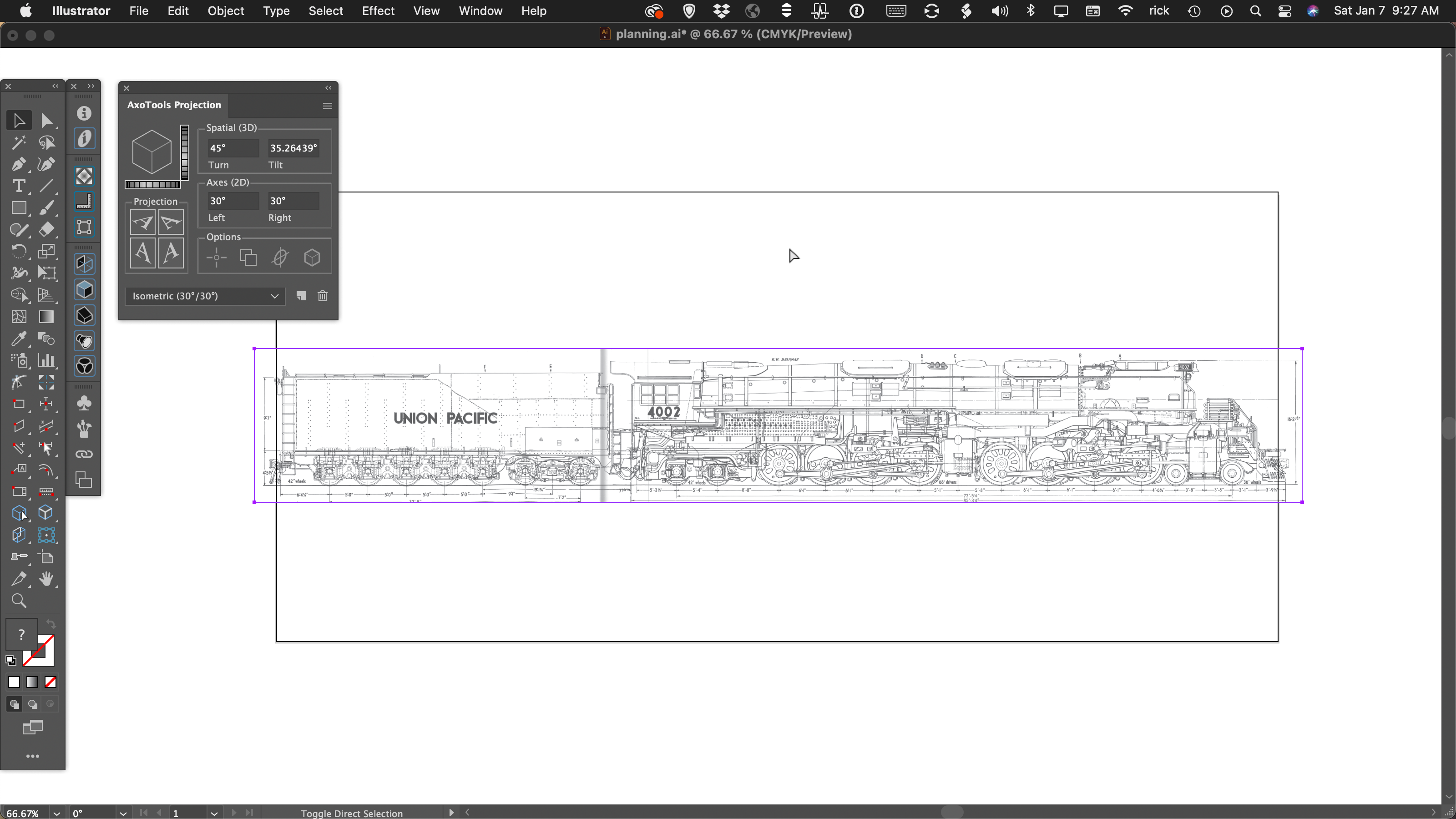
As I expected, isometric wouldn’t work well at all.
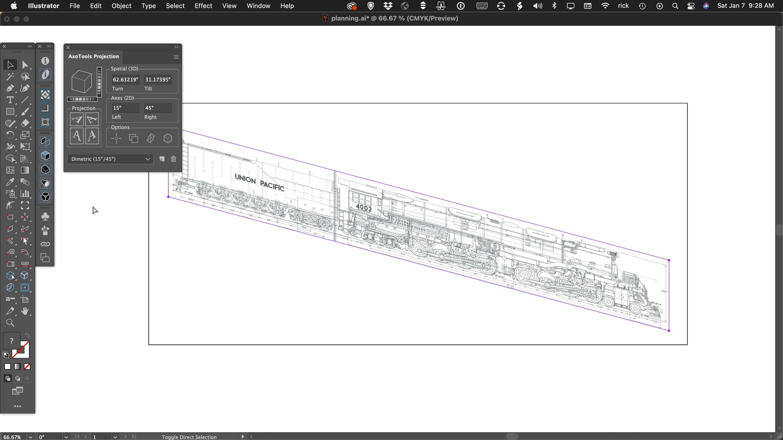
Dimetric with angles of 15 and 45 degrees seemed to work better, but you’ll need to repeat these steps with the top and end views to be sure if there’s really room for them.
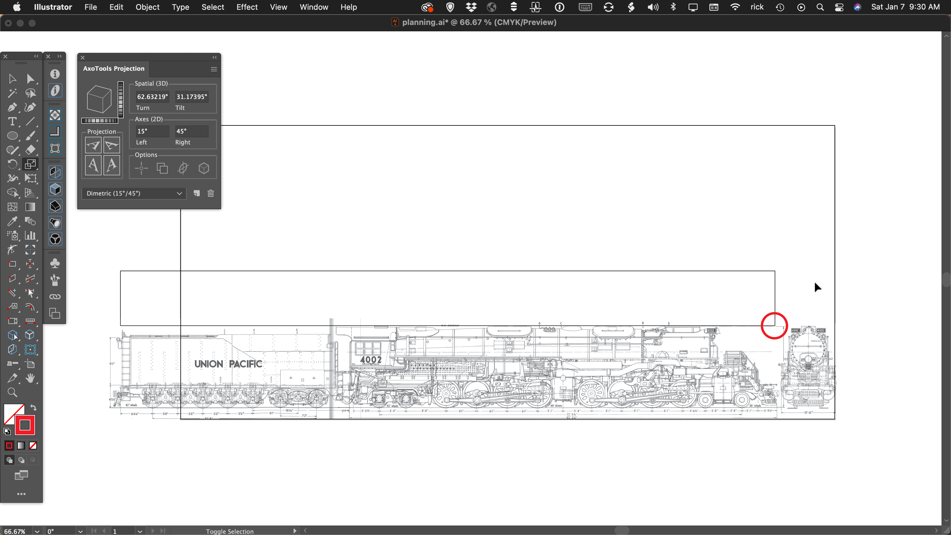
AxoTools offers an interactive alternative to the trial-by-error approach, which takes all three faces into account. Position placeholders for the three planes like surfaces of a cardboard box, and note the corner where they all meet.
Select the top view and, in the Transformations, panel, click “Create Transformation Object.” With the Axo (move) tool, click in the corner where the three views meet to set its anchor there. Next choose the orientation Axo Top-Left or Axo Top-Right as is appropriate for your drawing. Your art will immediately conform to your current document projection in the Projection panel.
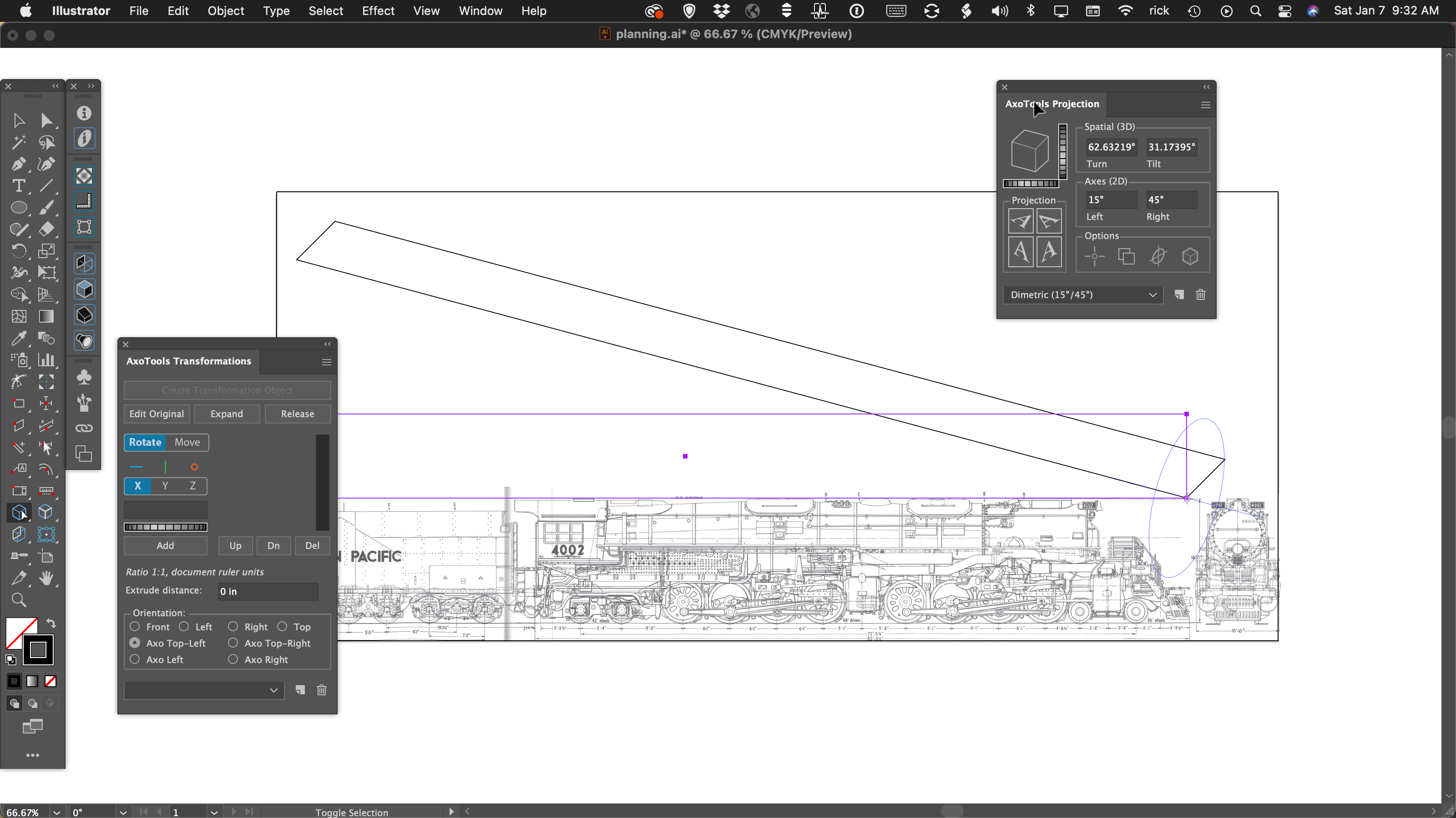
Now do the same for the left and right views, placing the anchor in the common point and setting their orientation to Axo Left and Axo Right.
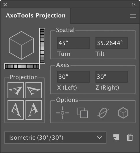
Now select the three faces and choose the menu item View > Hide Edges. In the Projection panel you can try different preset projections from the menu at the bottom of the panel, or for more fine-tuned results, change values in the axes or tilt/turn values, or drag the dial controls to find your best settings.
Now that you’ve established a projection that will fit, you can delete the placeholder art and begin drawing and projecting your final art with confidence.
I hope you find this useful.
![]()
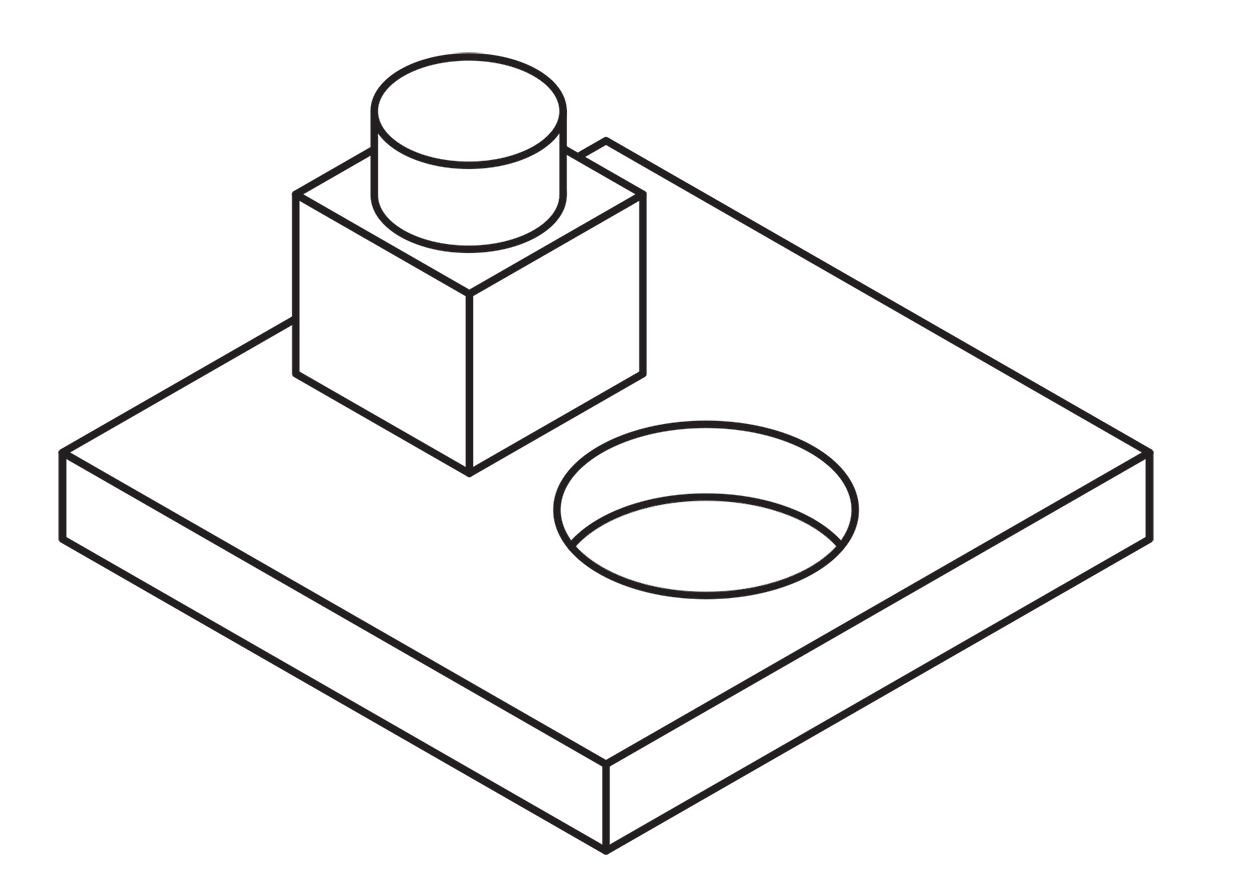 Using a single line weight (or “stroke width” as it applies to Illustrator’s path art property) is a simple and efficient way to work.
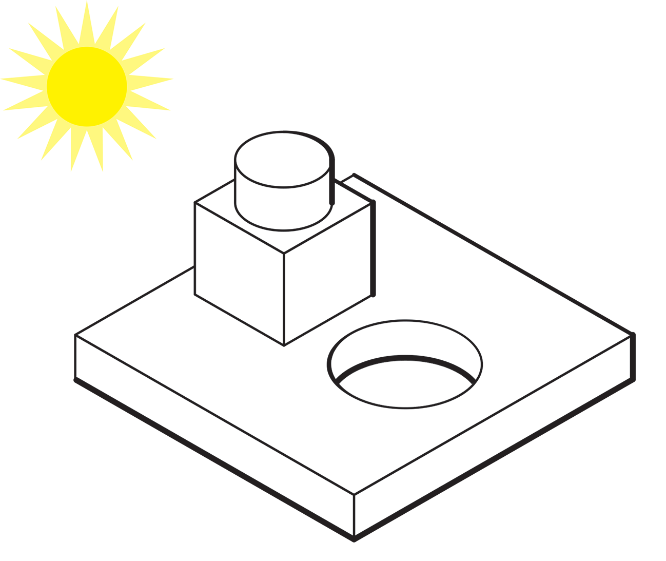
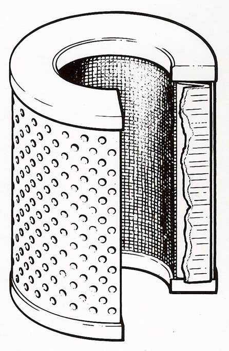
 Here’s an example of an illustration I did using the “Kalmbach” method, drawn in ink at 1.5 times reproduction size. Detail lines were drawn with a 4×0 Rapidograph pen, and the heavy lines were probably a no. 0 or 1 pen. In those days, we typically cut an Amberlith overlay to add a flat tint to the background, which helped separate the subject from the background.
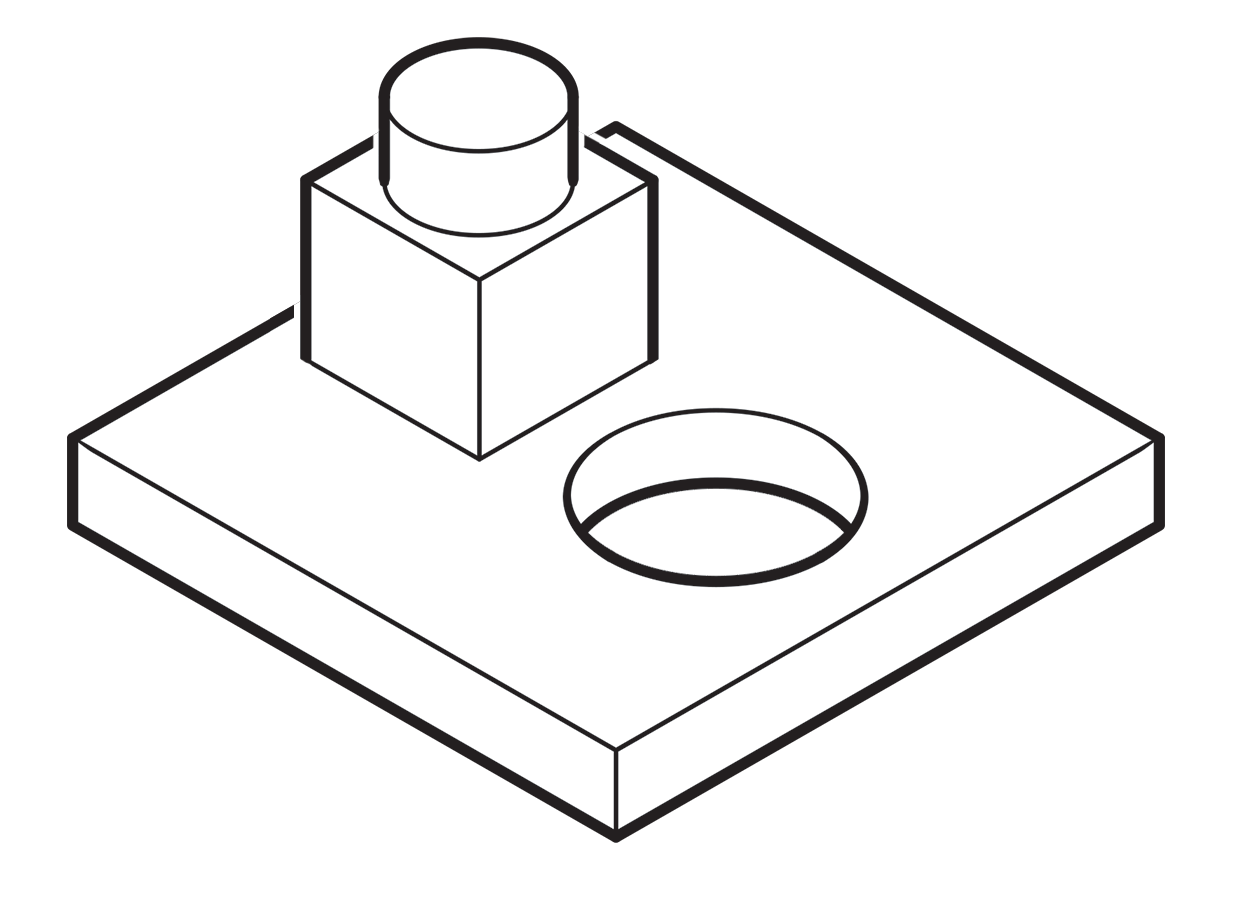 A more common method called “line contrast shading” used in exploded-view parts drawings uses heavier lines on all outside edges of objects. In this example, the bottom of the cube and cylinder are thin lines because they represent the joint between two surfaces. A heavy line would suggest the objects float above the other art. In the case of the round hole, a varied line width makes a smooth transition between the front- and rear-facing edges. Complex illustrations can use three or four line weights. Standards are more like guidelines, actually, that vary between people and between businesses, often based largely on the personal preference of someone with experience and/or influence.
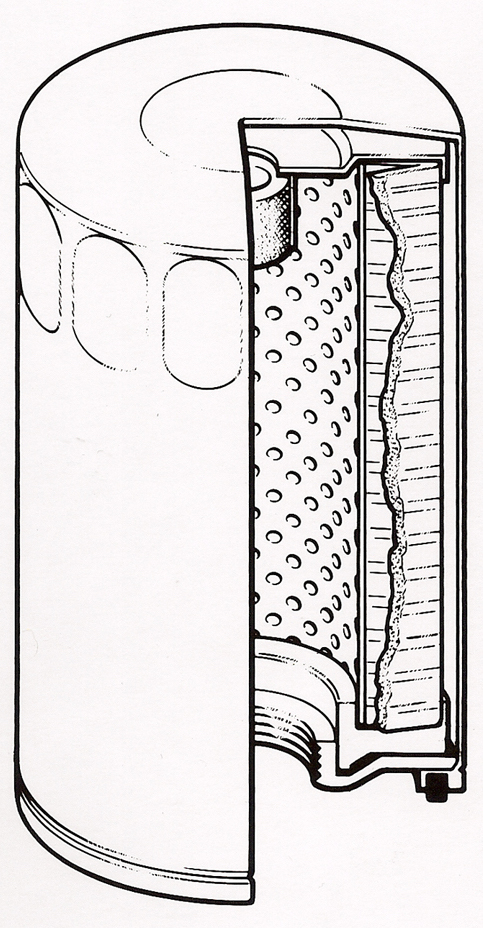
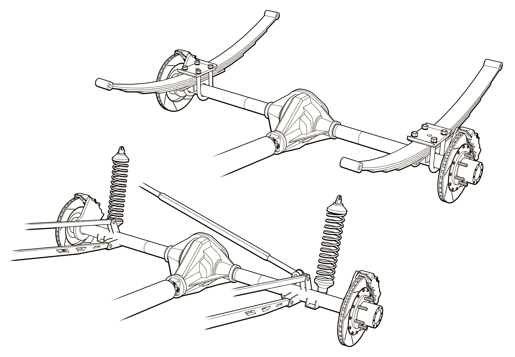 Greg used a three weight treatment on this Raptor suspension illustrations for Car and Driver magazine.
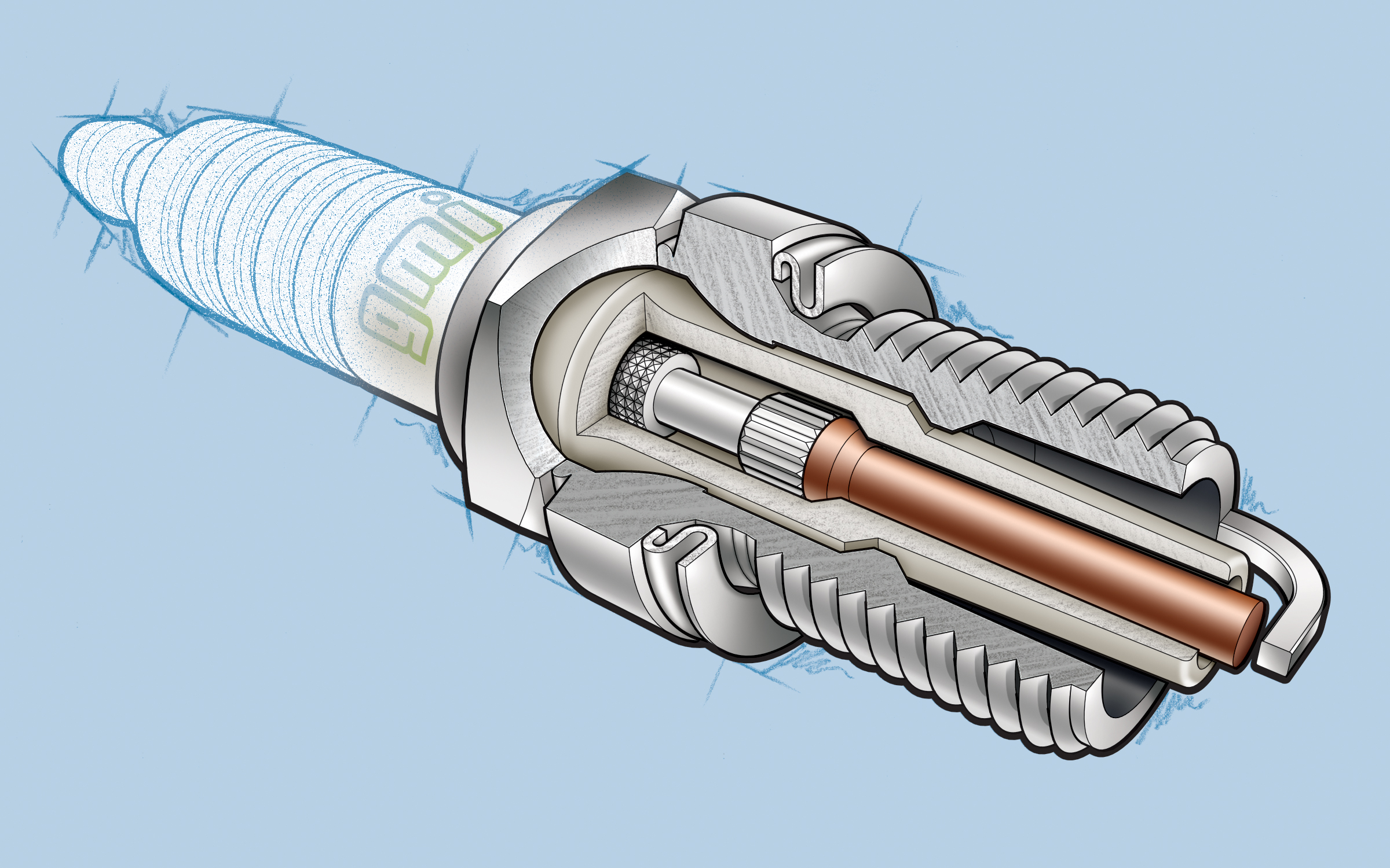 One more piece by Greg Maxson shows his skill at technical illustration using a variety of software, often including SketchUp, Illustrator, and others. Here he adds clarity to the subject with varied line weights, line colors, sometimes sketchy line treatments, and meaningful shading and textures in filled areas.
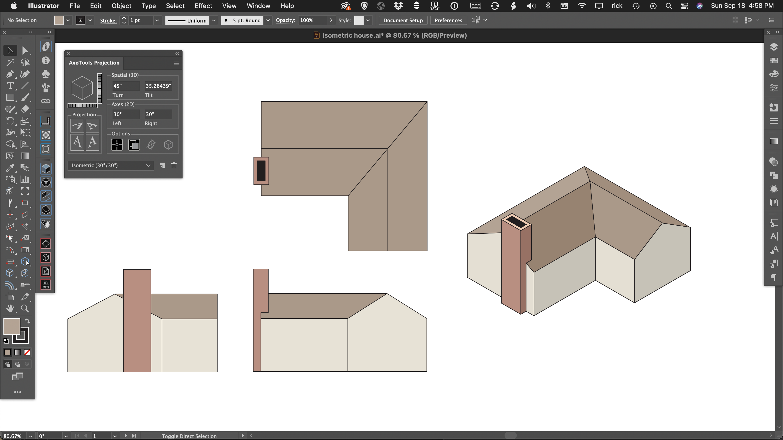


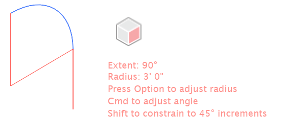 As you drag with the Axo Arc tool, the arc will appear highlighted. You can drag the arc forward or backward, left or right. Guide lines will appear to show the location of the arc center as well as a tangent line of the arc’s exit angle. If your preferences select Help text, the tool will also display the current arc’s extent angle and radius.
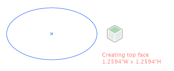 As you drag with the Axo Ellipse tool, the ellipse will appear projected onto your current axonometric plane. If your preferences select Help text, the tool will also display the current width and height using the units specified in your preferences and scaled to your document scale.
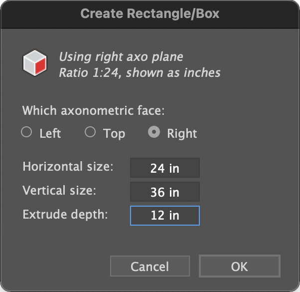
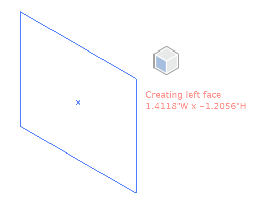 The Axo Rectangle tool works similar to the Axo Ellipse tool, except that it draws a rectangle. Like the Axo Ellipse tool, pressing the Shift or Alt/Option keys work as they do in Adobe Illustrator’s built-in Ellipse or Rectangle tools, only the art is drawn on an axonometric plane.