Using an auxiliary view in AxoTools
Update: Now with AxoTools 16.2, there’s an easier way!
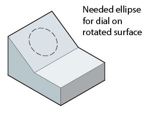
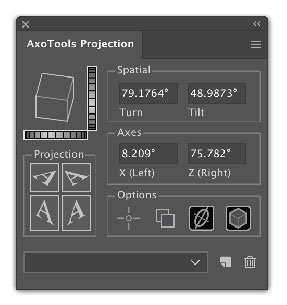
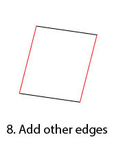
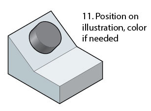
Every technical illustrator, it seems, eventually runs into a situation where a surface they’re drawing doesn’t exactly match the top, left, or right views. If one edge of a rectangle that defines that surface coincides with the X or Z axis, there are at least two ways to project that angled face. Let’s say you want to add a dial or knob to this control panel.
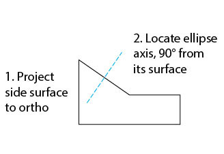
In conventional drafting, you’d draw what’s called an auxiliary view for the tilted panel, then mathematically calculate the locations of the panel’s elements in the axonometric (or isometric) view. One way might be called the “rotate and force-fit” method.
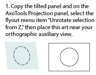
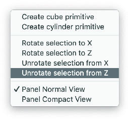
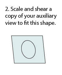
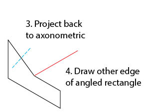
Here’s a sequence of steps that shows how that works, and illustrates the reason those four “Rotate” and “Unrotate” items were added to the flyout menu.
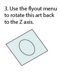
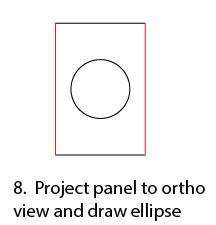
Of course, the axis of the ellipse is at a different angle than any axis, so here’s a method that uses axonometric logic to reverse-engineer the projection of that surface in order to use the Extrude tool to accurately draw the cylindrical shape of the knob.
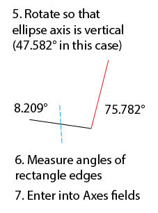
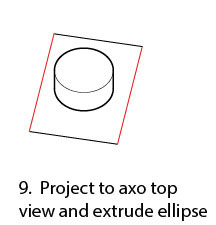
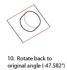
After this technique, be sure to restore your axonometric projection to the previous settings!
New tools are currently in progress for AxoTools, but until they’re available, this should help you get through some of those unusual situations.
If you have other tips, please share!
![]()


 Buried not-too-deeply in Adobe’s SDK (Software Developer’s Kit) is a list of pre-defined art object types. While some were included in Illustrator’s Select > Object menu, many more were not. It seemed useful to select the other object types, as well, and objects such as paths had properties that were easily obtained and often helpful to select within an illustration. In that spirit, I wrote Select Menu plugin and, given that it was relatively simple to build and applicable to casual users, I’d make it available for free.