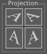
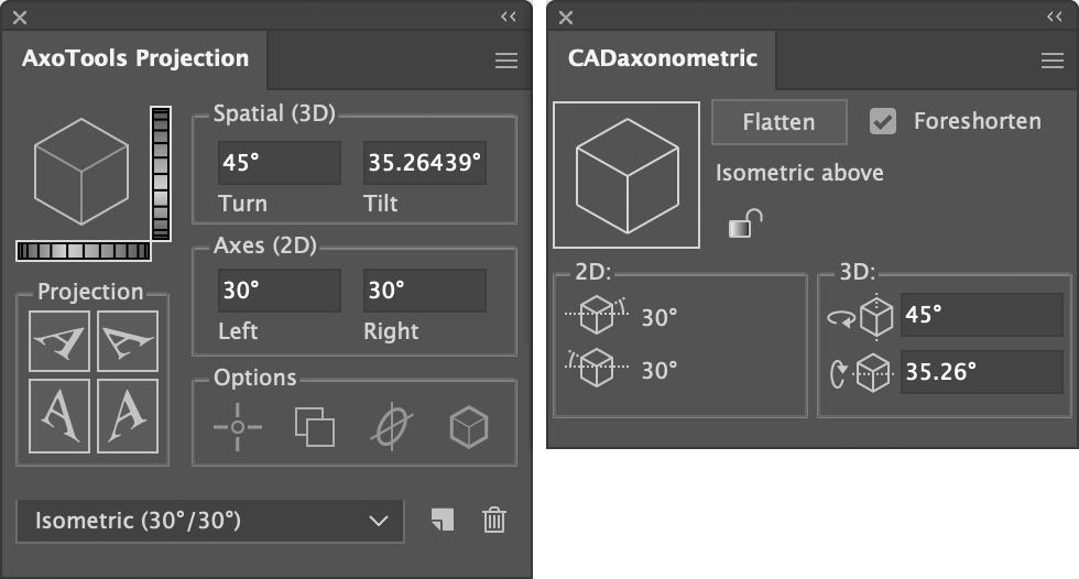
Projection panel
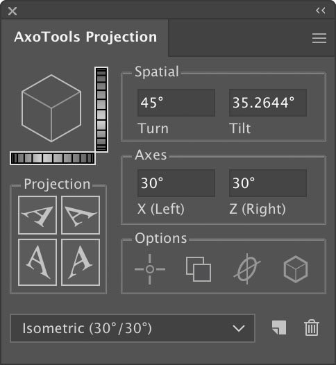
AxoTools’ primary panel is the AxoTools Projection panel. Open it by selecting Window > AxoTools > AxoTools Projection. Some features will only be visible when a document is open. This is the panel where you’ll define the angles of your finished illustration. AxoTools supports isometric, dimetric, and trimetric views, including bottom views.
The image in the upper-left corner displays a cube projected using the current settings.
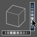
Adjusting the projection visually
To adjust the settings visually, click and drag in either of the “dial” controls to adjust Tilt and Turn. The control will turn from gray to color to show that it’s active and adjusting your settings.
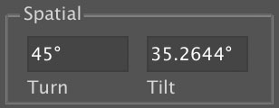 Adjusting the projection numerically
In the “Spatial” control area, define your view by entering values or moving the sliders.
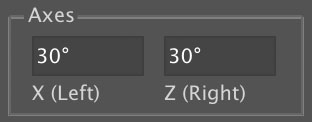 Alternatively, you can set the axis values in the “Axes” section.
Any projection must show at least part of two or three faces, so Tilt is limited to the range between 89° and -89°. Turn is limited to the range 0° through 90°. Left and Right axes are limited to the range between 88° and -88°. If an axis value is entered that is incompatible with the corresponding axis, the corresponding axis will be adjusted to the largest valid value.
Using presets for projection settings
You can also set the axis settings by selecting a preset in the popup/dropdown menu. To define a new preset, set your values, either using Turn/Tilt or X/Z axis, then click the “New” preset button. A dialog will appear in which you can name your preset and save it. To delete the current preset, click the Trash icon. Presets will be saved with your preferences and available in the current and future sessions.
Compact Projection panel
The settings for defining the view can be hidden by selecting “Panel Compact View” in the Projection Panel’s flyout menu, described below. That would leave visible only the buttons that relate directly to projecting selected art.
Projecting art
To project selected orthographic art to an axonometric plane, click one of the four Projection buttons corresponding to the transformation you want. The two buttons on the bottom represent the left and right planes. The two on the top both project to the top plane, but one orients it so that its geometry is aligned with the left face, the other aligned with the right face.
To un-project selected art, click the button on the corresponding plane while pressing the Shift key.
To project a copy of the selected art, press the Option or Alt key while clicking.
Art can also be projected using menu commands found under Object > Transform > Project to Axonometric. These menu items can be given custom keyboard shortcuts, which may be simpler and faster than using the panel.
 Options for projecting
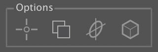
You can control some of the panel’s behaviors by clicking a quick-preference icon.
![]() The first icon will set the panel to project the art according to any defined Reference Points. Leave this option off to project the art anchored to the art’s selection center.
The first icon will set the panel to project the art according to any defined Reference Points. Leave this option off to project the art anchored to the art’s selection center.
![]() The second icon will tell AxoTools to always project a copy of your selected art. You can project a copy of the selected art by pressing Alt/Option while clicking the Project button, but if the Always Copy option is chose, Alt/Option will reverse that setting and project the original art.
The second icon will tell AxoTools to always project a copy of your selected art. You can project a copy of the selected art by pressing Alt/Option while clicking the Project button, but if the Always Copy option is chose, Alt/Option will reverse that setting and project the original art.
![]() The third icon sets whether circles are projected with their anchor points aligned to the X and Z axes, or aligned to the major and minor axis of the ellipse to aid in creating cylinders.
The third icon sets whether circles are projected with their anchor points aligned to the X and Z axes, or aligned to the major and minor axis of the ellipse to aid in creating cylinders.
![]() The fourth icon determines how stroke and fill are applied to projected art. With this option off, art will retain its original properties. With this option enabled, the art will be given the stroke and fill options in the Draw Settings panel.
The fourth icon determines how stroke and fill are applied to projected art. With this option off, art will retain its original properties. With this option enabled, the art will be given the stroke and fill options in the Draw Settings panel.
Also see Preferences.
For a step-by-step example of projecting artwork using reference points, please click the button below. Project-in-place is a critical component of AxoTools!
Flyout menu
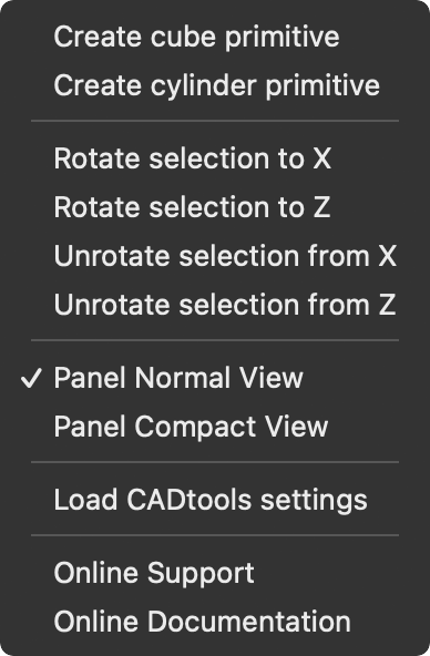 The Projection panel has a flyout menu that can be shown by clicking the widget in the upper right-hand corner of the panel. Some of these items are also located in the main menus, but are repeated here for your convenience.
Create cube primitive and Create cylinder primitive are simplified versions of the Object > Create Axonometric Primitives… menu item. Primitives are created without a dialog box to specify dimensions, at a size relative to your screen dimensions. The stroke and fill are applied according to your Draw Settings panel.
The four Rotate selection items are actually holdovers from before the Axo Shear tool was created. They were left here in case there is an occasion where this is still useful.
Panel Normal/Compact View switches the Projection panel’s contents to include or exclude the controls for changing the projection. Buttons for projecting art and enabling the projection options are alway available. See Getting Started for more information.
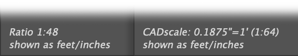
Load CADtools settings will import the Projection settings and scale from CADtools from Hot Door, regardless of whether your preferences are set to automatically use CADtools settings. See the section on CADtools integration below.
Online Support will open the Support web page for Graffix plugins.
Online Documentation will open the web page with online documentation for your plugin.
CADtools integration
 AxoTools can import projection settings and scales from the CADtools plugin from Hot Door. To enable this, first select one or both of the CADtools options in AxoTools’ Preferences dialog.
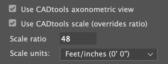
To import CADtools’ scale or projection settings as set in its CADaxonometric panel, first ensure that you have CADtools version 11 or higher installed. Next check the AxoTools preference to use CADtools axonometric view.
With these preferences set, AxoTools will automatically look for CADtools settings to import every time you open or change documents. CADtools does not notify AxoTools if its scale or projection is changed, so you make those changes in CADtools, you should also manually update the CADtools settings by selecting “Load CADtools settings” from the flyout menu in AxoTools’ Projection panel.
After importing the CADtools axonometric view settings, the axes of the CADaxonometric and AxoTools Projection panel should match, as well as the Tilt and Turn settings.
CADtools supports bottom-view projections, while AxoTools does not. If you try to import a bottom-view projection, you will get an error dialog.
If you have checked Use CADtools scale, then AxoTools will honor the CADtools document scale rather than the document scale ratio set in AxoTools’ preferences. The scale units you select in AxoTools will remain in effect, however, regardless of the units used in CADtools.
The imported CADtools scale will be shown wherever the current document scale ratio is displayed. In this example, at the bottom of the Axo Info panel for the Axo Measure tool, the document scale ratio is set to 1:48 (1/4″ = 1 foot), as shown on the left. In the panel on the right, CADtools has the scale set to 3/16 = 1 foot, so when the preferences are set to use the CADtools scale, it is used instead of the AxoTools setting.