Perspective projection
Here are some steps you can follow to project a set of orthographic top and side views to your perspective grid.
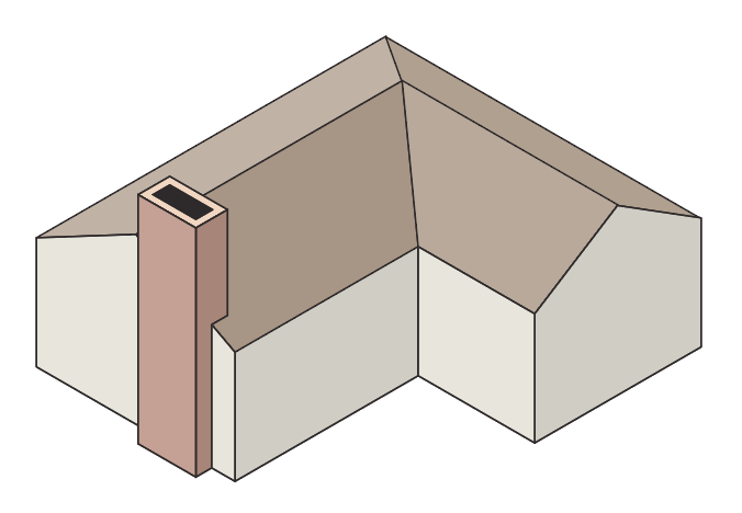
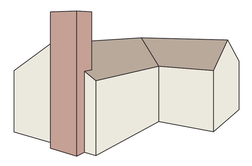
You may recognize this house drawing from the isometric projection project. In some ways, project it to isometric is even simpler.
![]() First, set up your perspective grid. Two- or three-point perspective is recommended. Next, we must prepare the orthographic top and side views using the Axo Zone tool. With the perspective grid visible, we will have options in the Zone tool that are specific to perspective projection.
First, set up your perspective grid. Two- or three-point perspective is recommended. Next, we must prepare the orthographic top and side views using the Axo Zone tool. With the perspective grid visible, we will have options in the Zone tool that are specific to perspective projection.
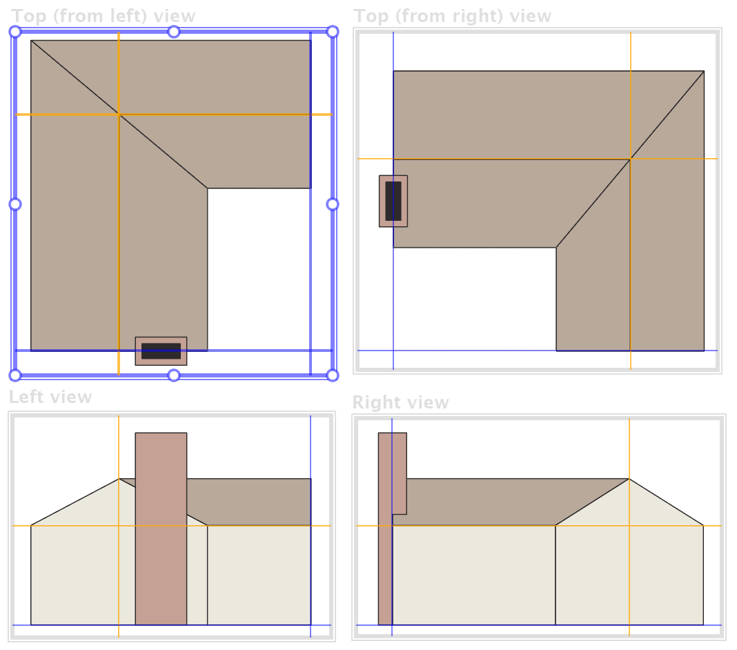
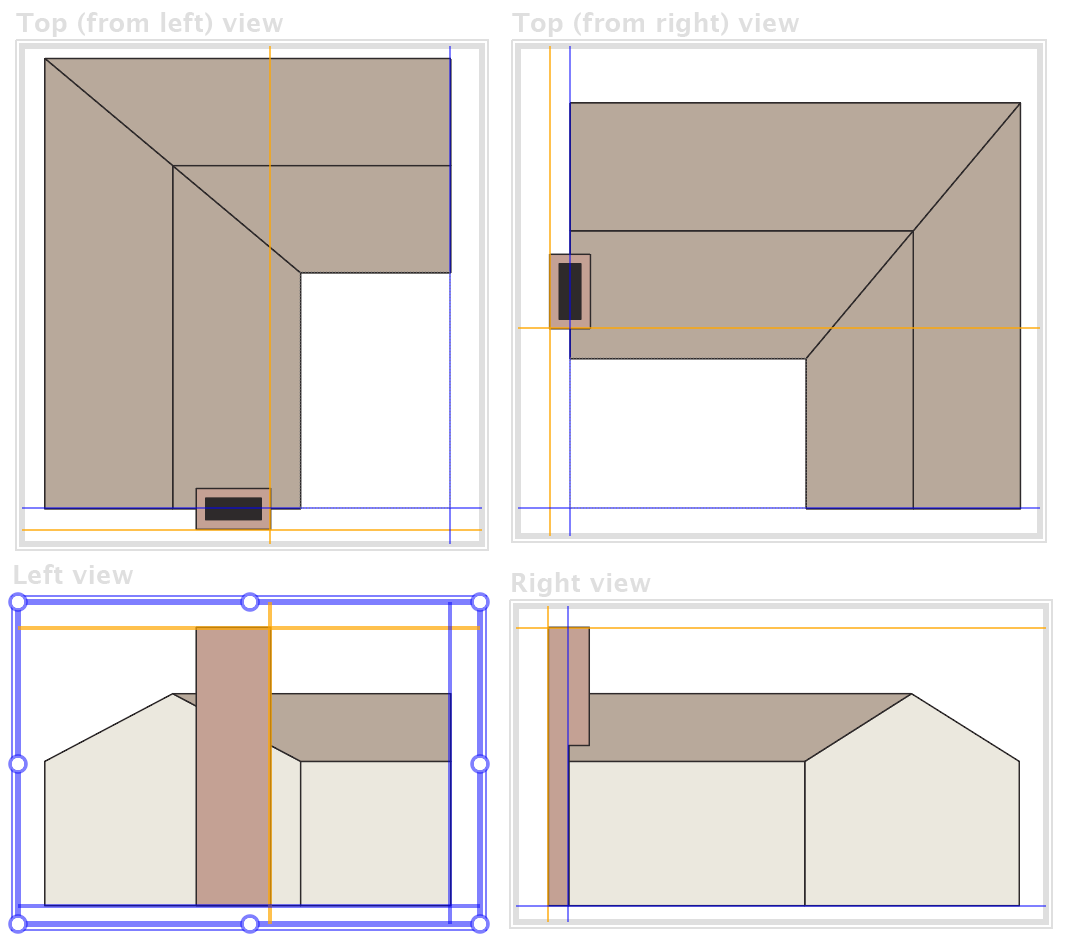
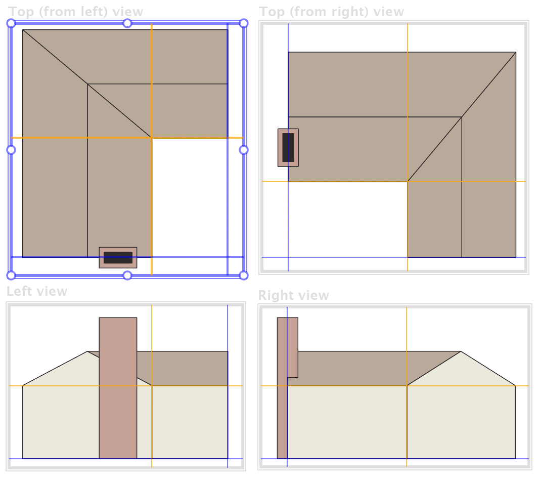 With the Zone tool, drag rectangles around the two side views and either one or both top views. In the dialog that appears, identify which view each represents.
When the surfaces are projected, they will be placed relative to the faces of the perspective grid, so you need to identify the grid plane in relation to your drawings. This is usually easiest if you have guides at those locations that your cursor can snap to.
In the top-left view, the left and right grid planes intersect in the lower right corner, where you see the blue lines. Shift-click to indicate that location. Repeat that in each of the other views.
To project the surfaces that are offset back from the face of the perspective grid plane, Alt/Option-click on a point at the inside corner of the house. Offset planes are always relative to the grid planes, so when you define, say, a right plane, it will automatically appear in other views where it shows. It will be helpful to also define a vertical offset at the base of the roof.
It’s important to keep in mind that when working with perspective, we have reference planes, not reference points. The Zone tool will define perspective planes when the perspective grid is visible, otherwise it creates reference points. If you’re getting unexpected results, check if your isometric grid is visible.
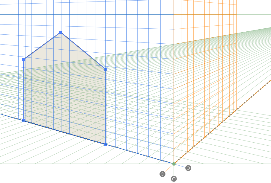 On the perspective panel, enable both options to enable reference points/planes, and to always copy art. Select the left wall with the peak and click on the Project Left button. Note that there is space between the wall and the outside of the grid box for the two inside walls.
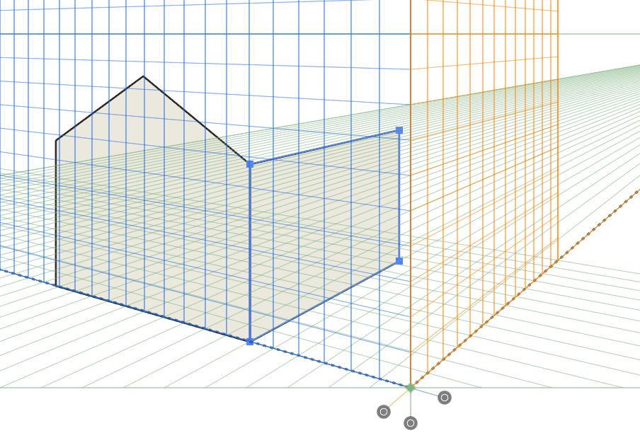 Select the wall next to it and Shift-click on the Project Right button. This aligns it with the perspective grid and offsets it back relative to the orange line in the top and left views.
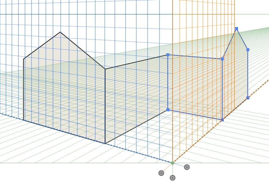 Now repeat that process with the remaining walls.
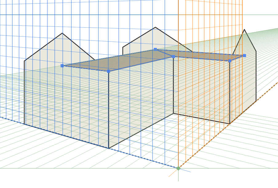
 Projecting the roof at their inclined planes is not possible with the current Perspective panel, but it’s easy to work around it. First, move your offset (orange) plane markers in the top view by Alt/Option-clicking on the intersection of the four roof sections.
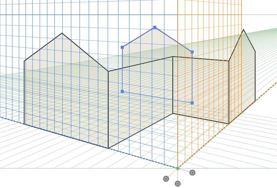 Select either one of the outside walls and Shift-click on the corresponding Project button. This will serve to temporarily indicate the correct location of all points visible on the roof.
 Select the visible roof panels and Shift-click the Project Top button that corresponds to the view with your selected art.
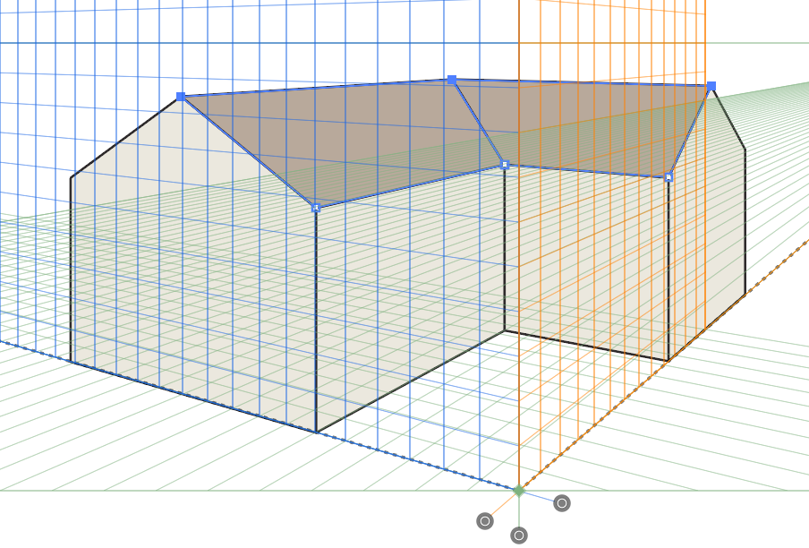 With the Direct Selection tool, select the top edges of the roof and drag them to the points at the top of each wall peak. You can now delete the temporary wall piece.
 Now prepare to project the chimney by moving your offset planes to match the chimney. If your perspective angle is high enough to show the top of the chimney, you’ll want to Alt-Option click at the top corner of the chimney, otherwise any location on the front corner of the chimney will work.
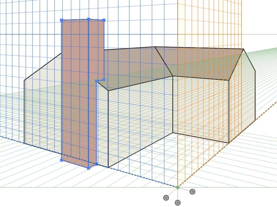 Select each chimney surface and Shift-click to project it offset into position.
If you are used to working with AxoTools’ axonometric functions, there are some caveats you need to be aware of.
- Perspective projection cannot use shading or multiple line widths because the projected art is handled internally by Adobe Illustrator.
- For the sane reason, there is no Extrude function in perspective.
- When moving, drawing, or selecting art, Adobe’s native functions are still active and may “hijack” your actions. Sometimes it’s helpful to toggle the perspective grid off, either by clicking the None button on the Perspective panel, o pressing Illustrator’s keyboard shortcut Cmd/Ctrl-I.
- When working in one-point perspective, there technically is no right plane, so right projections are sent to the left. To move art to the “right side of the street” you will have to drag it using Adobe’s Perspective Selection tool, while holding the 5 key. The art will then appear backward, but you can reflect it with the Perspective panel.